
Vehicle light

Inactive Publication Date: 2007-06-07
STANLEY ELECTRIC CO LTD
View PDF2 Cites 5 Cited by
  • Summary
  • Abstract
  • Description
  • Claims
  • Application Information

AI Technical Summary

Benefits of technology

[0017] Therefore, according to an aspect of the disclosed subject matter, a vehicle light can be provided which increases the diffusion angle of light to be irradiated in the emitting direction of the vehicle light. According to another aspect of the disclosed subject matter a vehicle light can be provided that has improved light utilization efficiency.
[0018] In particular, according to an aspect of the disclosed subject matter a vehicle light can be configured soas to realize an increase in the light diffusion angle of the diffusion light to be irradiated in the emitting direction of the vehicle light and to improve the light utilization efficiency in comparison with the case where the vehicle light irradiates only refracted light that previously passed through the diffusion plate in the emitting direction.

Problems solved by technology

However, a light loss of typically 10 to 20% has occurred due to the provision of the grouped lens 106 that has lens cuts.
This reduces the light utilization efficiency.
Accordingly, it is difficult to sufficiently diffuse the light with large angles in the irradiation direction using the vehicle light in accordance with the technique of Publication 1.
Accordingly, it is difficult to sufficiently diffuse the light with large angles in the irradiation direction using the vehicle light in accordance with the technique of Publication 2.
This reduces the light utilization efficiency.
Accordingly, it is difficult to sufficiently diffuse the light with large angles in the irradiation direction using the vehicle light in accordance with the technique of Publication 3.
Furthermore, the emitting surface thereof may be corrugated.
This is because the light incident on the incident surface at an angle less than 25° may be reflected and returned back toward the light source side, which is not effectively utilized for irradiation.

Method used


Image

  • Vehicle light
  • Vehicle light
  • Vehicle light

Examples


Embodiment Construction

[0048] The term “left (or left side)” used herein refers to the left side of the vehicle when seen from the front of the vehicle and at the passenger side, and the term “right (or right side)” refers to the right side of the vehicle when seen from the front of the vehicle.

[0049] It should be appreciated that the disclosed subject matter can be applied to a vehicle light such as a vehicle headlight, a vehicle auxiliary light, spot light, traffic lights, and the like. Hereinafter, a headlight may be exemplified in order to describe the disclosed subject matter.

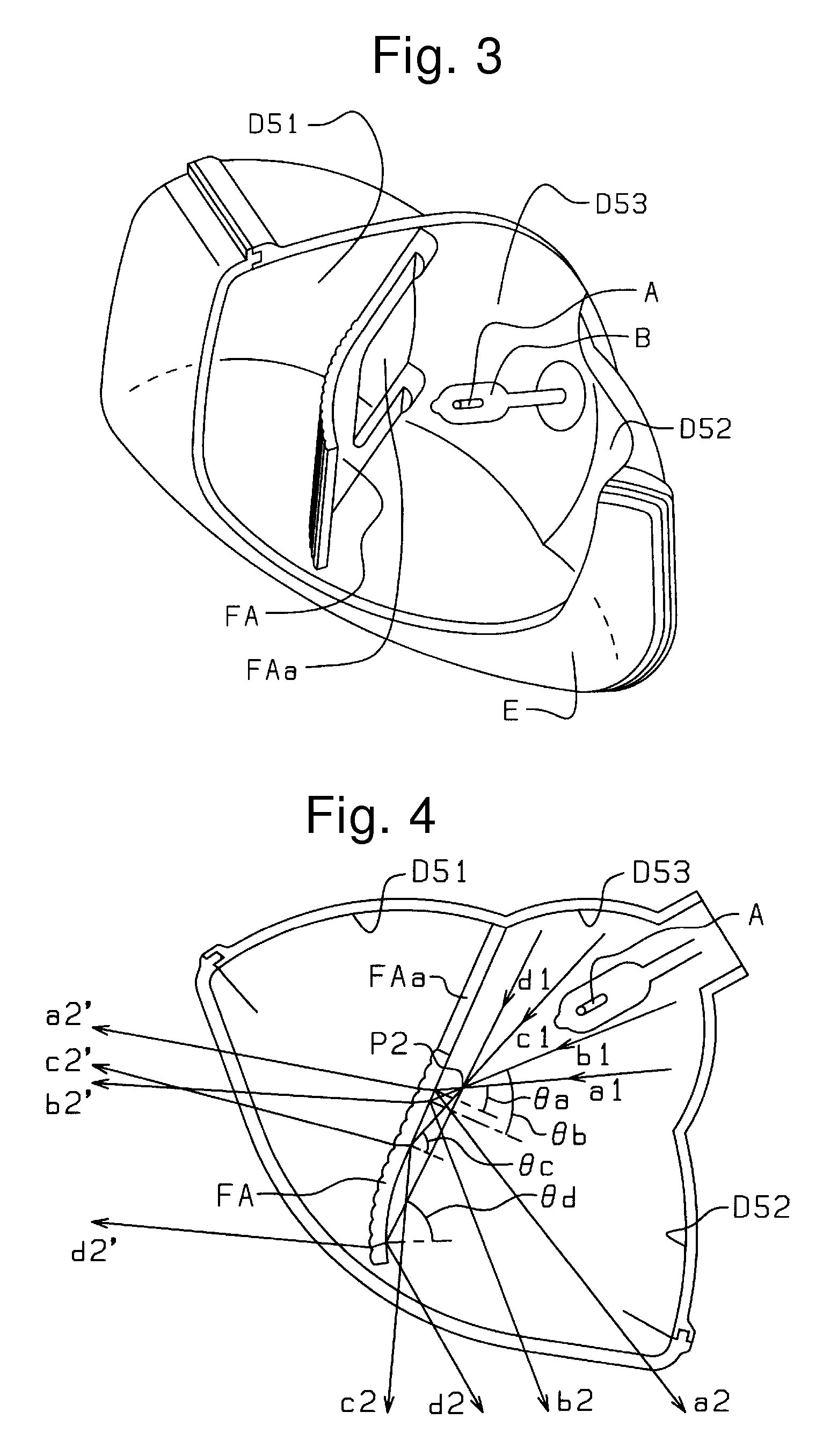
[0050] An exemplary embodiment of the disclosed subject matter will be described in detail with reference to FIG. 3, which is a perspective view of an embodiment of a vehicle light made in accordance with principles of the disclosed subject matter, and which is partially cut. In particular, FIG. 3 is a perspective view of a vehicle headlight for a right-side traffic system, as seen from above and from the front. FIGS. 4 and 5 ...


PUM


Abstract

A vehicle light can include a light source, a reflector configured to reflect light emitted from the light source in an irradiation direction of a vehicle on which the vehicle light is mounted, and a diffusion plate for diffusion of light and which can irradiate light in the irradiation direction. In this configuration, the diffusion plate can be configured such that light emitted from the light source and light reflected by the reflector enter the diffusion plate and pass therethrough while being refracted. The light is emitted from the diffusion plate in the irradiation direction while being diffused. At the same time, light which is incident on the diffusion plate and is reflected by the diffusion plate is diffused and irradiated in the irradiation direction of the vehicle light. The end portion of the diffusion plate can be bent or curved so as to diffuse the light reflected by the diffusion plate.

Description

BACKGROUND [0001] This application claims the priority benefit under 35 U.S.C. § 119 of Japanese Patent Application No. 2005-352881 filed on Dec. 7, 2005, and Japanese Patent Application No. 2005-376132 filed on Dec. 27, 2005 which are hereby incorporated in their entirety by reference. [0002] 1. Field [0003] The disclosed subject matter relates to a vehicle light such as a vehicle headlight, a vehicle auxiliary light, spot light, traffic light, and the like, having a diffusion plate for diffusing light. In particular, the disclosed subject matter relates to a vehicle light which can widen the diffusion angle of light that is irradiated in an emitting direction of the vehicle light, thereby improving the light utilization efficiency. [0004] Furthermore, the disclosed subject matter relates to a vehicle light which can widen the diffusion angle of light being irradiated in an emitting direction of the vehicle light, thereby improving the light utilization efficiency in comparison wit...

Claims


Application Information

Patent Timeline
IPC IPC(8): B60Q1/00
CPCF21S48/1233F21S48/1388F21S48/2212F21S48/23F21S41/162F21S41/285F21S41/321F21S41/323F21S41/337F21S41/365F21S43/13F21S43/26F21S43/31F21S43/40F21S41/28F21S43/30
Inventor OYAMA, HIROO
Owner STANLEY ELECTRIC CO LTD
Learn More