

Watch whose movement includes a constant force device
a constant force device and movement technology, applied in the field of watches with mechanical movements, can solve the problems of substantial loss of advantages due to constant force driving the escapement, and achieve the effect of facilitating the reading of the tim
- Summary
- Abstract
- Description
- Claims
- Application Information
AI Technical Summary
Benefits of technology
Problems solved by technology
Method used
Image

Examples
Embodiment Construction
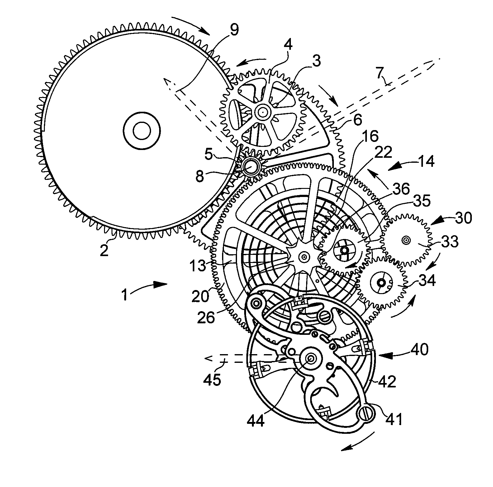
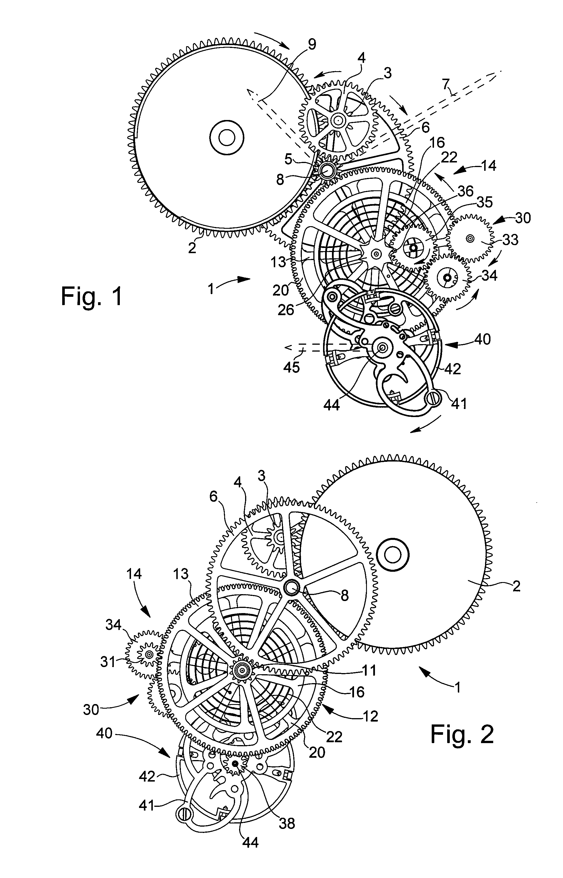
[0016] In the movement of watch 1 shown in a simplified manner in FIGS. 1 and 2, a spring barrel 2 drives in rotation the pinion 3 of an intermediate wheel 4, called the eight day wheel, which meshes with the centre pinion 5 of a centre wheel 6 completing one revolution per hour. The presence of intermediate wheel 4 in this example is not directly connected to the invention; it is due to the fact that movement 1 comprises several complications that are not shown and that have to be driven by barrel 2, which is provided with a longer spring and which rotates more quickly than ordinary barrels. The spring barrel can be wound manually or automatically. As in a conventional movement, a cannon-pinion carrying the minute hand 7 is friction mounted on arbour 8 of centre wheel 6 and rotatably carries an hour wheel carrying an hour hand 9. For the sake of clarity, only the hands of the time display device are shown in the drawings, in a very schematic manner.
[0017] Centre wheel 6 meshes on ...
PUM
 Abstract
Description
Claims
Application Information