Parallel moving device, actuator, lens unit, and camera

a technology of parallel moving and actuators, applied in the direction of mountings, instruments, camera body details, etc., can solve the problems of deteriorating controllability of parallel moving mechanism, complicated support mechanism of fixed frame, and difficulty in high-speed and linear parallel movemen

Inactive Publication Date: 2007-06-07
TAMRON
View PDF6 Cites 47 Cited by
  • Summary
  • Abstract
  • Description
  • Claims
  • Application Information

AI Technical Summary

Problems solved by technology

However, the conventional vibration-proofing device described in the above patent document has a problem that since the image blur is prevented by the parallel moving mechanism constructed by combining the guide unit arranged in the two directions orthogonal to each other and the driving units in those directions, a support mechanism of the fixed frame, and the holding frame can be complicated, for example.
And if the support mechanism becomes complicated, weight of a movable part of the parallel moving mechanism increases, there by making high-speed and linear parallel movement difficult.
Furthermore, since sliding resistance is generated between the parallel moving mechanism and the guide unit in the conventional vibration-proofing device, controllability of the parallel moving mechanism is deteriorated.
Therefore, unintentional movement in a space corresponding to this clearance may occur, thereby causing a positioning error.
In addition, if such clearance is provided, a load relating to driving is different between movement without contact between members and movement while sliding, thereby deteriorating control accuracy.

Method used


Image

  • Parallel moving device, actuator, lens unit, and camera
  • Parallel moving device, actuator, lens unit, and camera
  • Parallel moving device, actuator, lens unit, and camera

Examples


first embodiment

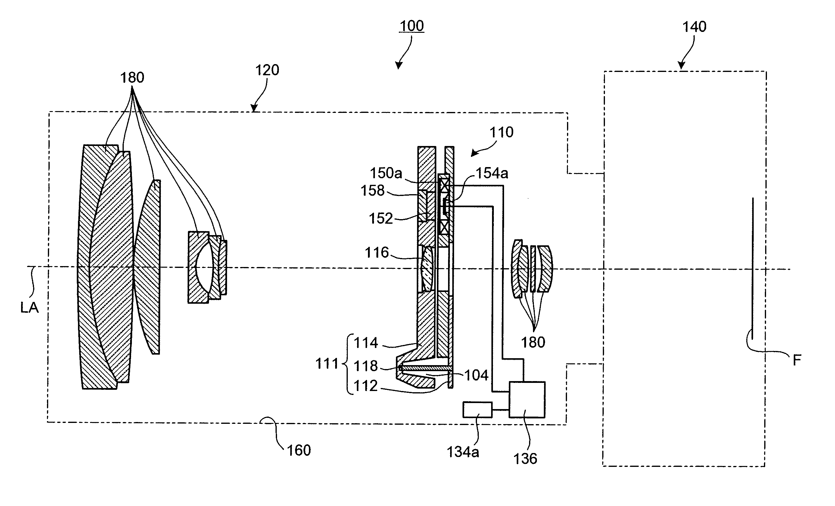
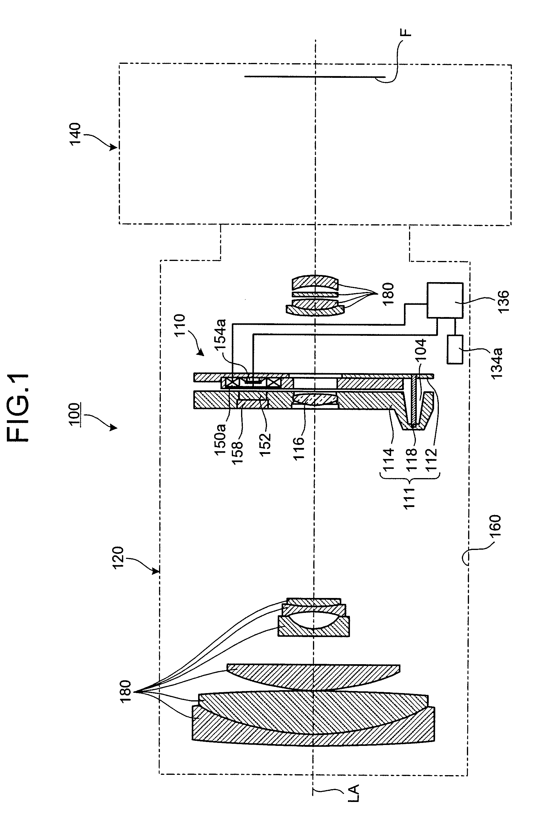
[0046]FIG. 1 is a cross-section of a camera according to the present invention. As shown in FIG. 1, a camera 100 includes a lens unit 120 and a camera body 140. The lens unit 120 includes a lens barrel 160 having an enclosure formed in a cylindrical shape, for example, an imaging lens 180 constituted of a plurality of lenses disposed inside the lens barrel 160, an actuator 110 that moves an image stabilizing lens 116 in a predetermined plane, and gyros 134a, 134b (only the gyro 134a is shown in FIG. 1) as a vibration detecting unit that detects vibration of the lens barrel 160.

[0047] In the camera 100 constructed as above, vibration of the lens barrel 160 is detected by the gyros 134a, 134b, and the actuator 110 is operated based on the detected vibration so as to move the image stabilizing lens 116 in an arbitrary direction in a plane in a direction substantially perpendicular to an optical axis LA so that an image focused on a film face F of the camera body 140 is stabilized. The ...

second embodiment

[0178] When the parallel moving device 200 according to this second embodiment is to be used, it is only necessary to have a driving force generated by an arbitrary driving unit to the moving frame 214, for example, so that the moving frame 214 is moved in a plane parallel with the fixed plate 212. At this time, the moving frame 214 is moved in parallel with the fixed plate 212 since the three columnar members 218 are defected and deformed in the moving direction.

[0179] Since the moving frame 214 is supported by the three columnar members 218 in parallel, sliding resistance or resistance caused by contact hardly act on the moving frame 214 at movement. Therefore, with the parallel moving device 200 according to the second embodiment of the present invention, since various resistances hardly act on the movement of the moving frame 214, the moving frame 214 can be moved with a small driving force.

[0180] An actuator according to a third embodiment of the present invention corresponds ...


PUM


Abstract

A parallel moving device includes a fixed plate provided on an enclosure side, a moving frame provided on an optical system side, and three columnar members that are provided between the fixed plate and the moving frame and that support the fixed plate and the moving frame so as to enable movement of the moving frame in a direction substantially perpendicular to an optical axis of the optical system. These columnar members are formed with an elastic member that connects the fixed plate and the moving frame in the direction along the optical axis and supports the moving frame in parallel with the fixed plate.

Description

BACKGROUND OF THE INVENTION [0001] 1. Field of the Invention [0002] The present invention relates to a parallel moving device, and an actuator, a lens unit, and a camera that includes the parallel moving device. [0003] 2. Description of the Related Art [0004] In a lens device provided with an imaging lens such as a variable magnification lens often employ a vibration-proofing device that prevents image blur caused by vibration due to hand jiggling, etc. In this type of vibration-proofing device, for example, the image blur is prevented by detecting vibration of a lens barrel housing an imaging lens, and by driving a correction lens on a plane parallel with a film so as not to cause the image blur based on the detected vibration. This type of vibration-proofing device is usually provided with a parallel moving mechanism that moves the correcting lens in parallel on a predetermined plane. [0005] This type of parallel moving mechanism has, for example, a structure as follows. The paral...

Claims


Application Information

Patent Timeline
Patent Type & Authority Applications(United States)
IPC IPC(8): G03B17/00
CPCG02B7/10G02B7/102G02B27/646G03B2217/005
Inventor IWASAKI, TAKAFUMINOJI, TAKAYOSHI
Owner TAMRON
Why Eureka
Try Eureka