Cardiac pacemaker with dynamic conduction time monitoring

a heart and dynamic technology, applied in the field of controlling the pacing of the heart, can solve problems such as optimal av delay

a heart and dynamic technology, applied in the field of controlling the pacing of the heart, can solve problems such as optimal av delay

US20070129762A1Inactive Publication Date: 2007-06-07WORLEY SETH

Image

  • Cardiac pacemaker with dynamic conduction time monitoring
  • Cardiac pacemaker with dynamic conduction time monitoring
  • Cardiac pacemaker with dynamic conduction time monitoring

Examples


Embodiment Construction

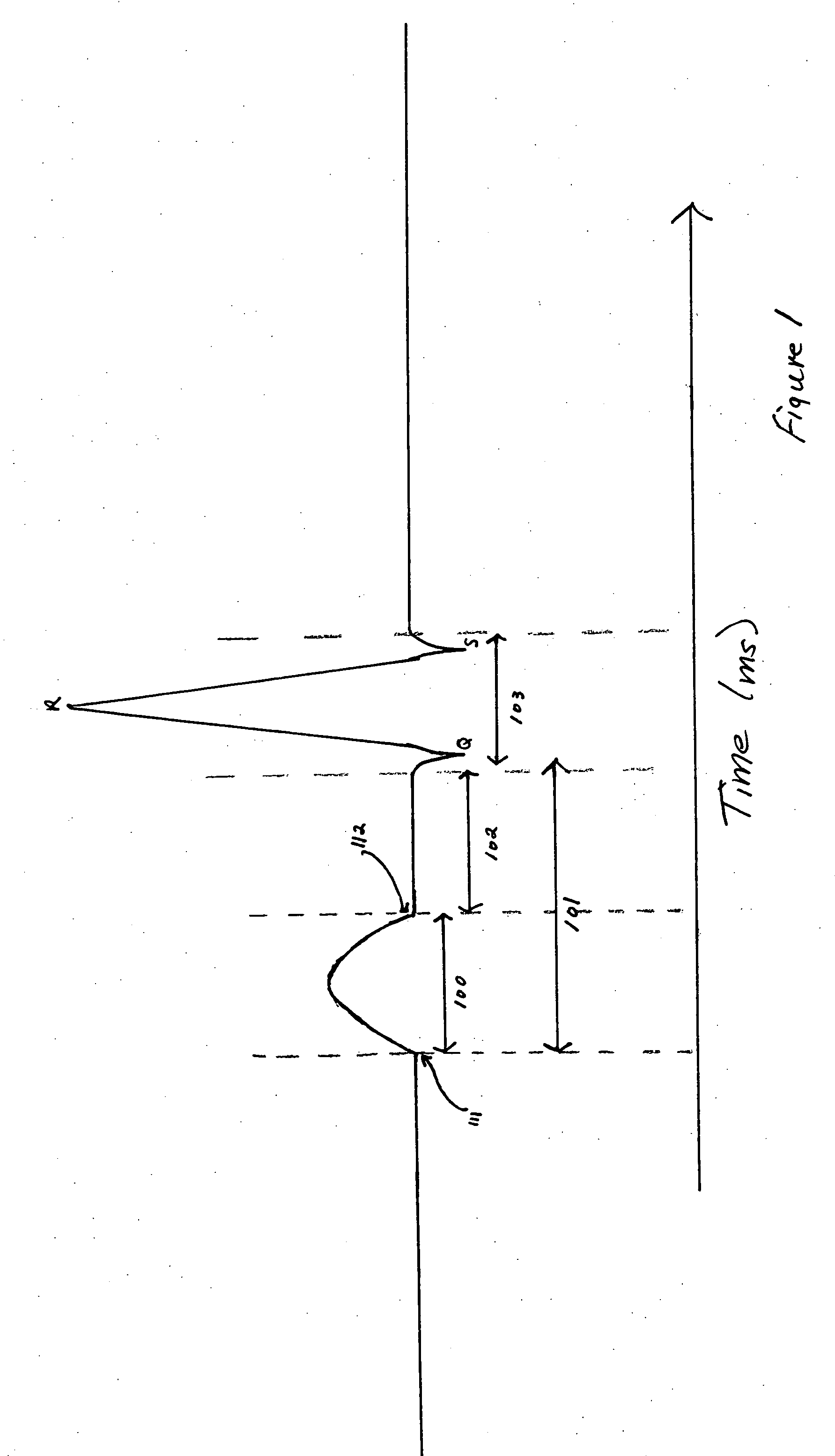
[0023] Referring to FIG. 1, which depicts the electrical activity of a heart as recorded by electrocardiography from the body surface, the P-wave 100 represents the wave of depolarization that spreads from the sino-atrial node through the atria on the body surface electrocardiogram (“ECG”). Said another way, the P-wave is the electrical activity generated by depolarization of the atrium as recorded on the body surface by the ECG. The duration of the P-wave in any one of the 12 leads of the ECG may vary according to position of the ECG lead relative to the electrical vector created by the depolarizing atrium. The P-wave usually ranges from 80 ms in duration to 100 ms in duration. The P-wave is generally measured from the onset of the pacing stimulus or activation 111 in one atrium to the end of atrial depolarization in another atrium. The duration of the P-wave in one lead of the ECG is that part of the total atrial activation that can be detected on the body surface from one vantage...


PUM


Abstract

In accordance with the present invention, a cardiac device is provided comprising a first electrode for sensing an electrical pulse in an atrium, a second electrode for sensing an electrical pulse in an atrium, a microcontroller coupled to the first electrode and the second electrode for determining time between the first and second pulses, and an electrode for stimulating a chamber of a heart wherein the stimulation is based on the first and second pulses.

Description


Claims


Application Information

Patent Timeline
07 Jun 2007
Publication
US20070129762A1