
Detachable lifting mechanism for a tracked snow vehicle method and apparatus

a technology of a vehicle and a lifting mechanism, which is applied in the direction of lifting devices, way cleaning, construction, etc., can solve the problems of difficult lifting of heavy chairs, which are now commonly removable from the main operating cable, and wood and metal are quite heavy

Inactive Publication Date: 2007-06-14
GOODMAN RON +1
View PDF9 Cites 24 Cited by
  • Summary
  • Abstract
  • Description
  • Claims
  • Application Information

AI Technical Summary

Benefits of technology

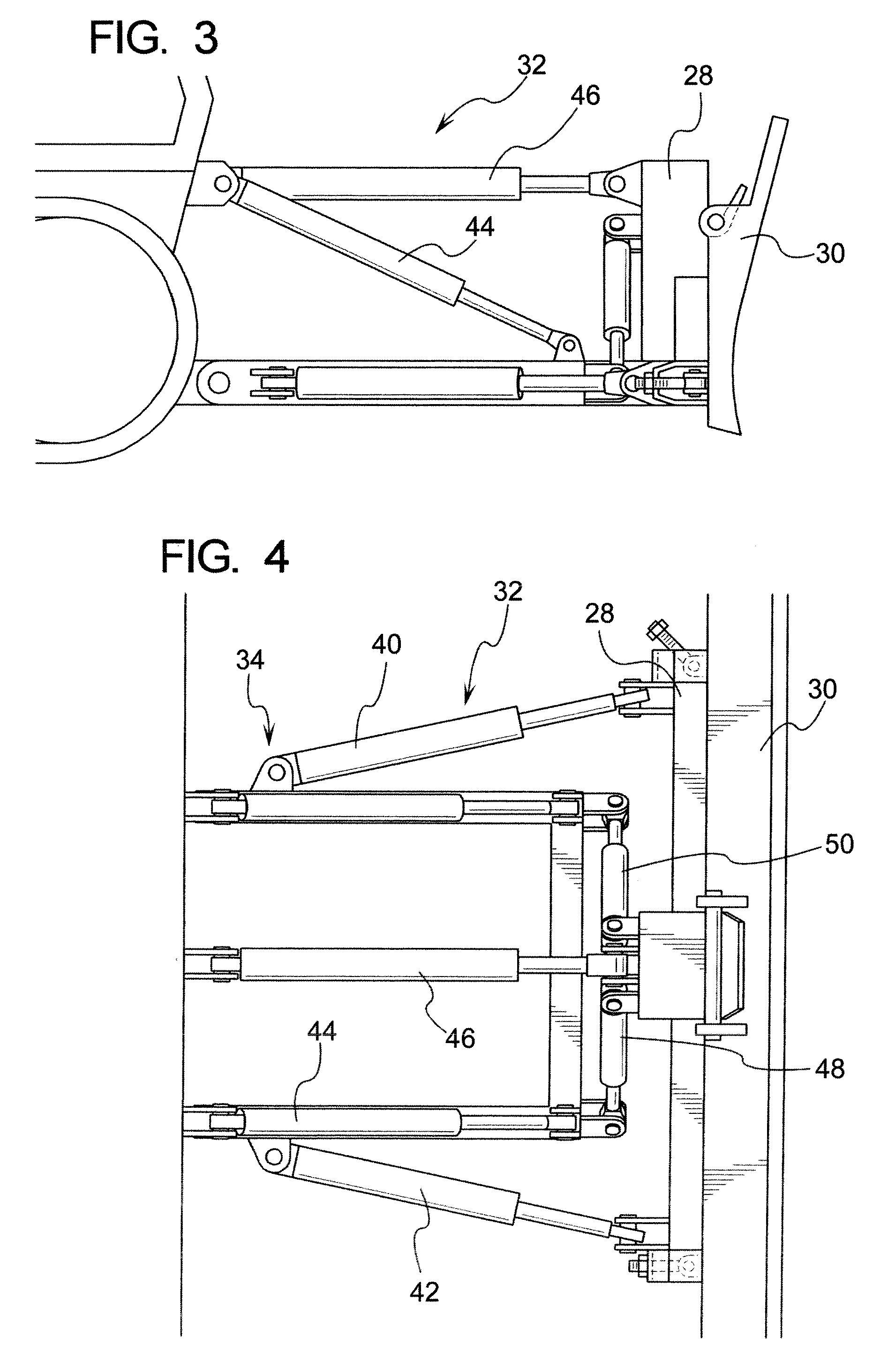
[0007] Disclosed below is a lifting device adapted to be positioned onto a over snow track vehicle where a positioning member and a control member is provided that is adapted to control a plurality of hydraulic lines. One pair of the hydraulic lines being adapted to normally operate one or more winglets. The lifting device comprises an interface member having connection portions adapted to engage the positioning member in a fixedly and removably attached manner. Further a hydraulic lift system is provided having a hydraulic line that is in fluid communication with a hydraulic actuator. The actuator being operatively connected to a repositioning member that is adapted to reposition with respect to the interface member. A base mount is provided having an attachment region that is adapted to be rigidly and removably attached to the interface member. One of the hydraulic lines that is controlled by the control member which normally controls one or more winglets is in communication with the hydraulic actuator.

Problems solved by technology

It has been problematic in certain environments such as ski resorts to reposition large, heavy or cumbersome items.
Such props can include rails, drops, wooden based jumps, etc. which are commonly constructed from wood and metal and are quite heavy.
In addition to the various uses noted above, chairlift maintenance is another concern, where lifting heavy chairs, which are now commonly removable from the main operating cable, can be a difficult task.

Method used


Image

  • Detachable lifting mechanism for a tracked snow vehicle method and apparatus
  • Detachable lifting mechanism for a tracked snow vehicle method and apparatus
  • Detachable lifting mechanism for a tracked snow vehicle method and apparatus

Examples


Embodiment Construction

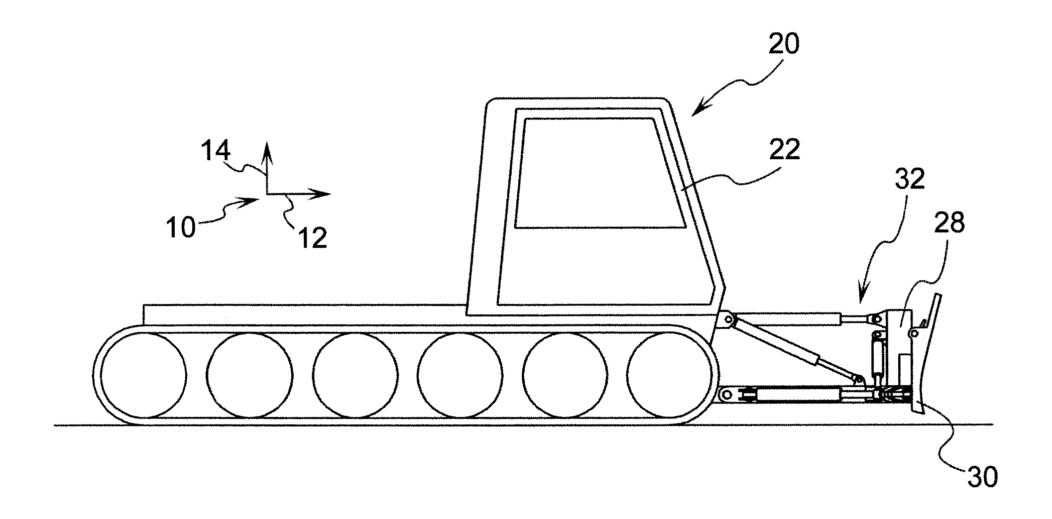
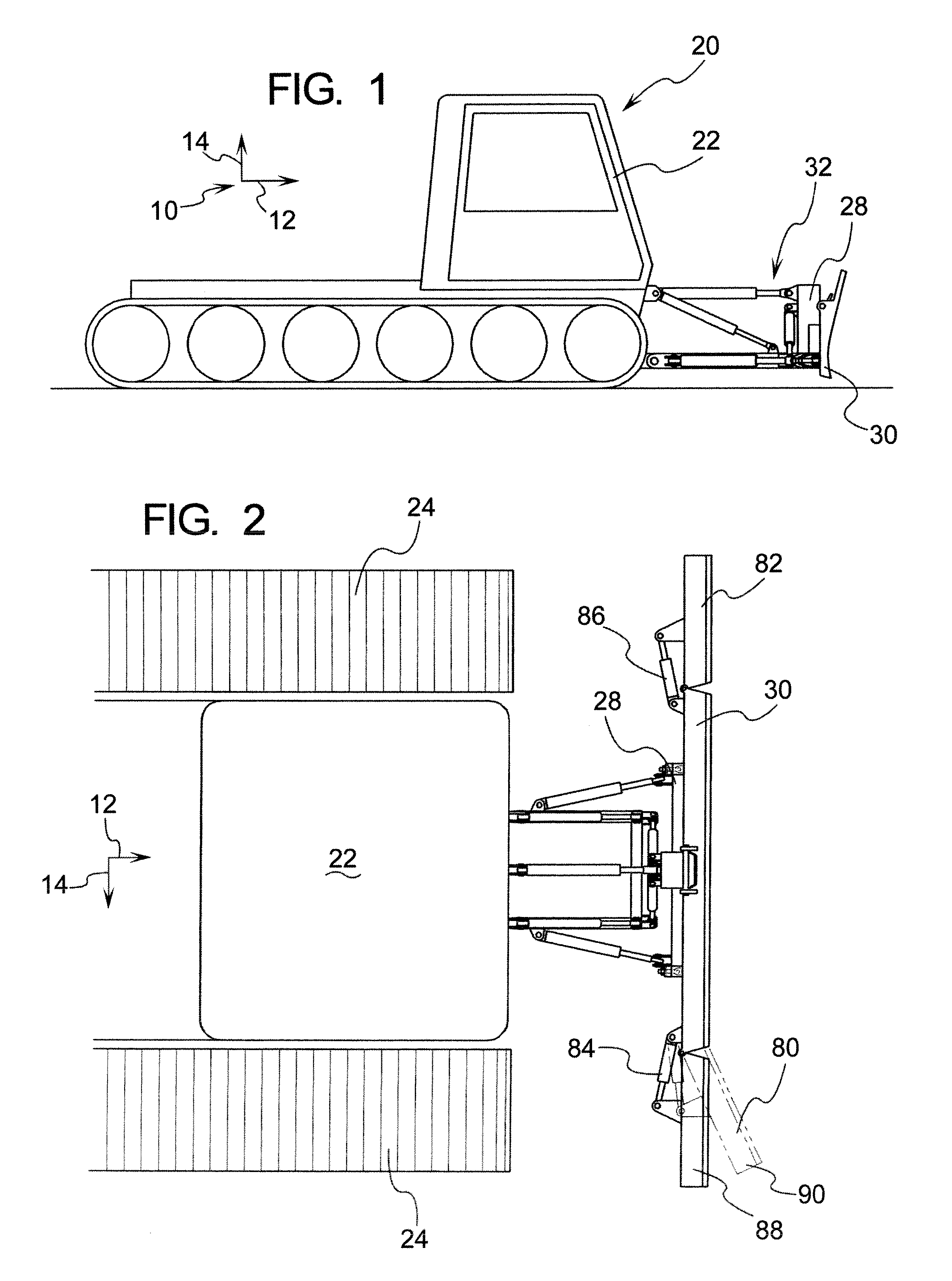
[0041] In general, the first drawings with reference to FIGS. 1-10 show various existing vehicles and structures relating thereto that are common in environments with large amounts of snow such as ski resorts, oil rig camps in the Arctic or in Alaska, etc.

[0042] To aid in the description, an axes system 10 is defined where the axis 12 indicates the longitudinal axis and the axis 14 shows a vertical axis. As shown in FIG. 2, the axis 14 indicates the lateral direction and more specifically points in a first lateral direction where the substantially opposing direction is referred to as the second lateral direction. There will now be a description of the snow track-type vehicle which is referred to as an over-snow track vehicle which the invention described below is adapted to operate in. It should be noted that the snow track-type vehicle device is shown in a somewhat schematic nature and can represent various commercially available snow track-type vehicles. In fact, a mounting plate...


PUM


Abstract

A lifting device adapted to be fitted to a tracked vehicle which is configured to operate in snow-covered terrain. The lifting device has an interface member which in one form allows for an interface portion of the mast region to fit to a plurality of commercially available tracked snow vehicles. Further, in one form, the lifting device interfaces with the existing hydraulics of conventional tracked snow vehicles.

Description

RELATED APPLICATIONS [0001] This application claims priority benefit of U.S. Ser. No. 60 / 750,817, filed Dec. 14, 2005.BACKGROUND OF THE INVENTION [0002] Ski lifts and other operations in the snow often require repositioning of the snow to groom slopes or otherwise clearing of the snow when desirable (such as clearing Arctic runways for planes). Snow track-type vehicles are commonly available and sold to ski areas, oil drilling operations, or any other type of commercial operation where there is a large quantity of snow and mechanical work is required in that area. Snow track-type vehicles commonly have an actuating system with a plurality of hydraulic members that are utilized to reposition a base mount. Oftentimes, the base mount is adapted to have a blade attached thereto. In one form, the blade has winglets which are hydraulically actuated to rotate about a substantially vertical axis in the lateral distal portions of the blade. Normally, the winglets are utilized by the snow tra...

Claims


Application Information

Patent Timeline
Patent Type & Authority Applications(United States)
IPC IPC(8): E01H5/04
CPCB66F9/065B66F9/08B66F9/10B66F9/122B66F9/125E01H5/06E02F3/7613E02F3/7618E02F3/815E02F9/2004
Inventor GOODMAN, RONGOODMAN, TERRY
Owner GOODMAN RON
Learn More