Valve with a rotated solenoid

Inactive Publication Date: 2007-06-14
NORGREN INC (US)
View PDF16 Cites 15 Cited by
  • Summary
  • Abstract
  • Description
  • Claims
  • Application Information

AI Technical Summary

Benefits of technology

[0010] A valve that has the solenoids aligned at an angle of 90 degrees with respect to the valve operator is disclosed. By aligning the solenoid at 90 degrees the fluid passageways in the valve operator are simplified and the operator body is easier to mold.

Problems solved by technology

Current valve islands have a number of problems.
One problem is the complexity of the fluid passageways that run between and connect the various components of the valve island.
The fluid passageways are difficult to manufacture and may limit the minimum size of the valve components.

Method used


Image

  • Valve with a rotated solenoid
  • Valve with a rotated solenoid
  • Valve with a rotated solenoid

Examples


Embodiment Construction

[0033]FIGS. 4-17 and the following description depict specific examples to teach those skilled in the art how to make and use the best mode of the invention. For the purpose of teaching inventive principles, some conventional aspects have been simplified or omitted. Those skilled in the art will appreciate variations from these examples that fall within the scope of the invention. Those skilled in the art will appreciate that the features described below can be combined in various ways to form multiple variations of the invention. As a result, the invention is not limited to the specific examples described below, but only by the claims and their equivalents.

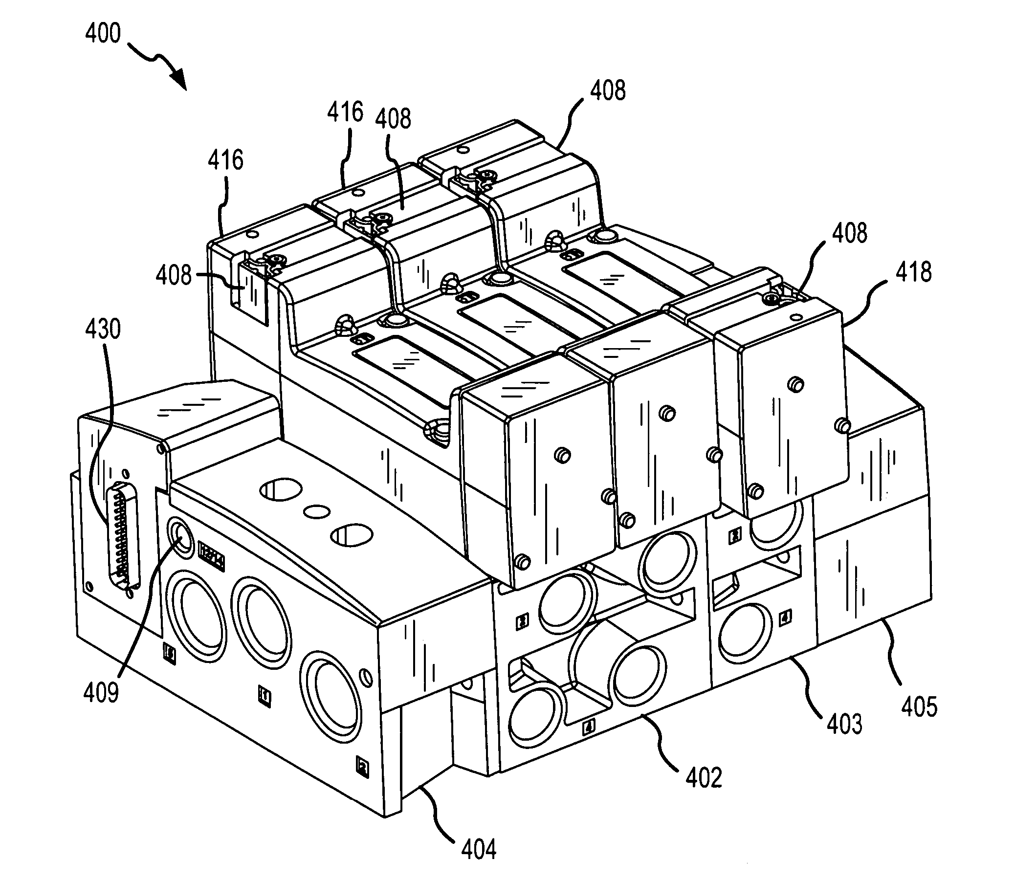
[0034]FIG. 4 is an isometric view of valve island 400 in one example embodiment of the invention. Valve island 400 is a 3 station assembly and comprises a double sub-base 402, a single sub-base 403, end plate 405, communication end plate 404, two single solenoid valves 416, a double solenoid valve 418, a main PC board 430, pilot...


PUM


Abstract

A valve that has the solenoids aligned at an angle of 90 degrees with respect to the valve operator is disclosed. By aligning the solenoid at 90 degrees the fluid passageways in the valve operator are simplified and the operator body is easier to mold.

Description

RELATED APPLICATIONS [0001] This application is related to applications “A valve island with a pilot air path located on the side of a sub-base”, “A valve island with non-active area venting between components”, “A valve island having the expansion PC board secured in the expansion station”, “A valve with an integrated PC board and connecting bar”, and “An alignment ramp for a PC board in an operator for a valve” filed on the same day as this application and included by reference into this application. BACKGROUND OF THE INVENTION [0002] 1. Field of the Invention [0003] The invention is related to the field of pneumatic controls, and in particular, to an improved valve island. [0004] 2. Description of the Prior Art [0005] Valve islands are typically considered to be a group of electrically operated pneumatic valves mounted on a common base with a common electrical wireway. Valve islands may also be manually or pneumatically controlled. FIG. 1 is an isometric view of a typical valve i...

Claims


Application Information

Patent Timeline
IPC IPC(8): F15B13/00
CPCF15B13/0814F15B13/0817F15B13/0825F15B13/0828F15B13/0832F15B13/0857F15B13/0867F15B13/0875F16K27/003F16K31/0675Y10T137/87885Y10T137/0491
Inventor ZUB, WALTER A.
Owner NORGREN INC (US)
Why Eureka
Try Eureka