Disc guide of disc carrying device

Inactive Publication Date: 2008-06-05
TANASHIN DENKI CO
View PDF16 Cites 0 Cited by
  • Summary
  • Abstract
  • Description
  • Claims
  • Application Information

AI Technical Summary

Benefits of technology

[0018]After each stopper is inserted into the large hole while the end of each guide projection overlapped onto the step difference, the guide projection is slid along the guide plate and the engagement projection is moved toward the small hole side and the overlap of each guide projection, eliminating the step difference, and each guide projection is secured to the guide plate.
[0020]According to the disc guide of a disc carrying device of the present invention, a metal plate, which is difficult to deform, is used for the guide plate, and a smoothly-slidable synthetic resin is used for the guide projections. In addition, the multiple guide projections made of a synthetic resin are easily mounted onto the guide plate by outsert molding, thereby obtaining the disc guide. Therefore, since a resin is not required to be attached and secured onto a portion of the metal plate by molding, molding can be easy and the disc guide can be produced at low cost.
[0021]Further, if the shape and the dimension of all the guide projections are the same, the guide projections can be produced by using a common metal mold; therefore, the production cost can be further lowered.

Problems solved by technology

In Japanese Laid-Open Patent Publication 2003-77198, since the disc plate and guide projections are integrally formed with a metal plate, sliding of the disc relative to the guide projections is poor and the disc may not be smoothly carried.
Moreover, there is another problem that since the disc makes contact with the metal guide projections, the disc can easily be damaged.
Further, in the configuration of Japanese Laid-open Patent Publication 2002-298481, because the guide plate is made of a synthetic resin, deformation, such as warping easily occurs at the time of molding and its strength is not sufficient, and when deformation occurs, the disc may not be smoothly carried.
However, since the outsert molding is used, it is necessary to attach and secure the resin to a portion of the metal plate by molding.
Hence, there is the problem that not only is molding difficult, but it is also costly.

Method used


Image

  • Disc guide of disc carrying device
  • Disc guide of disc carrying device
  • Disc guide of disc carrying device

Examples


Embodiment Construction

[0028]A preferred embodiment for implementing a disc guide 1 of the present invention is described hereafter, with reference to the drawings.

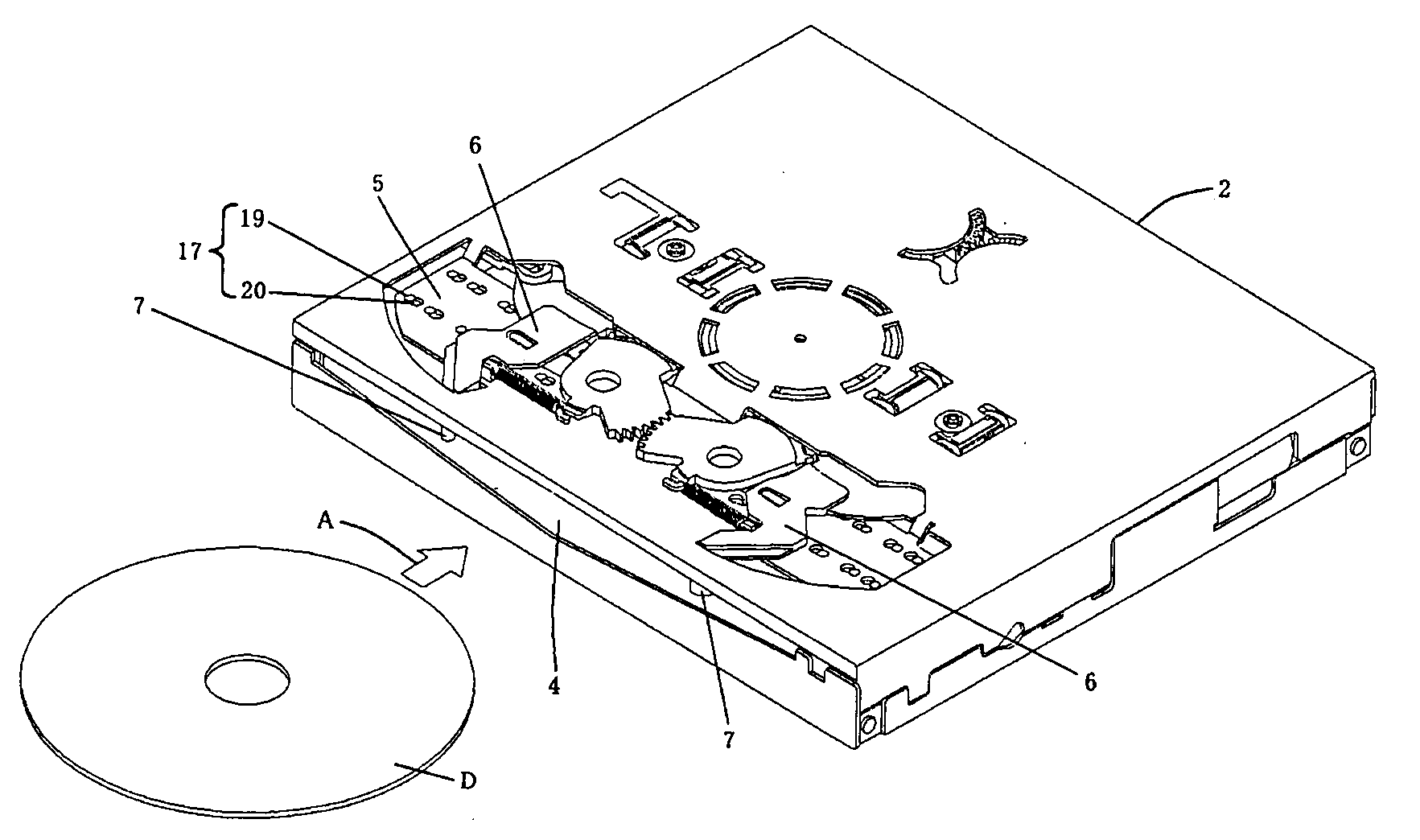
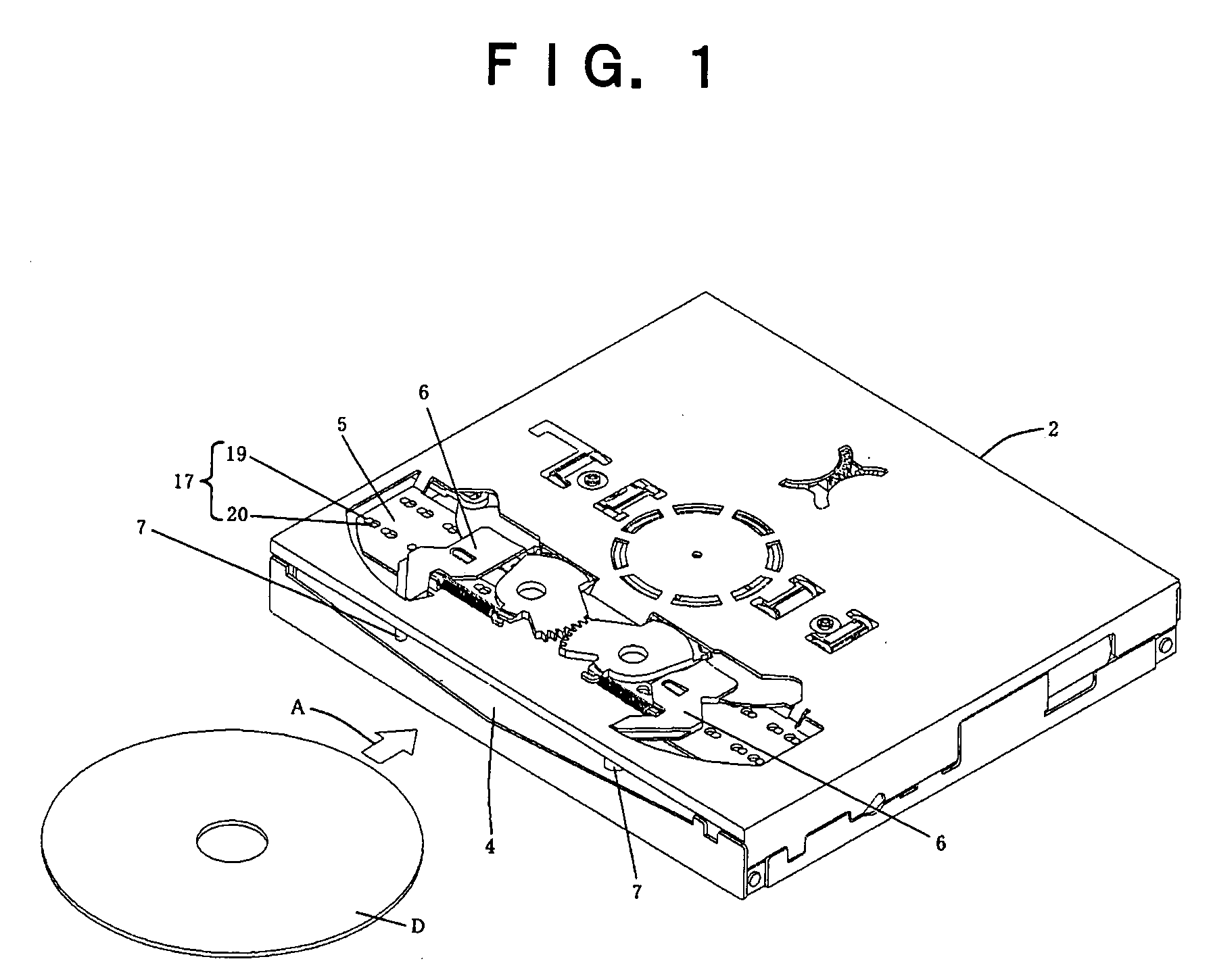
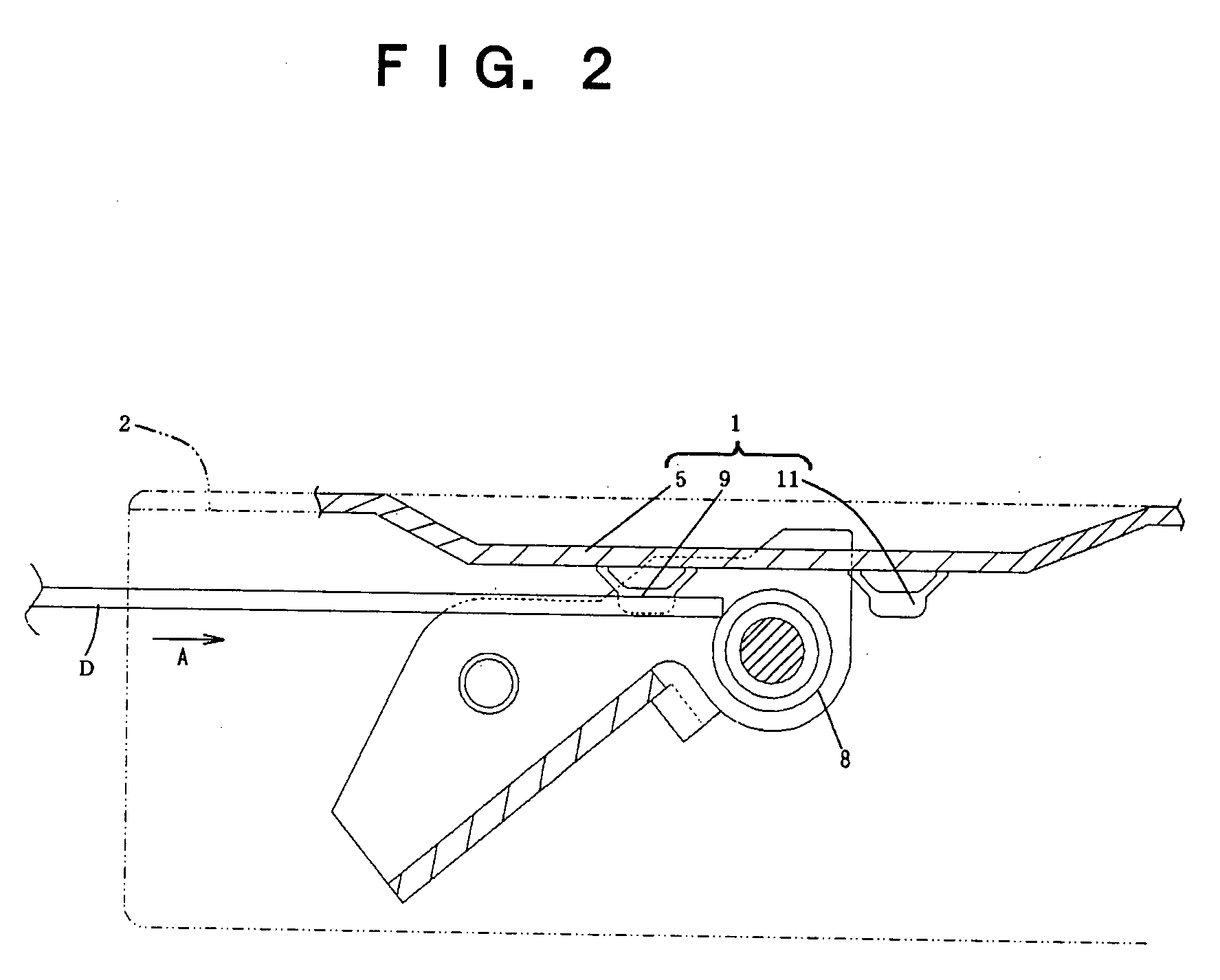
[0029]FIG. 1 shows a disc player with a built-in disc carrying device. FIG. 2 is a sectional side view of the periphery of the disc guide 1. As shown in FIG. 1, a top panel is arranged in a metal external chassis 2 of the disc player, and a damper (not shown) is mounted to the lower surface side substantially in the center. Further, a turntable (not shown) is arranged at the lower side position of the clamper within the external chassis 2.

[0030]A disc insertion slot 4 is placed on the front panel of the external chassis 2. The symbol A in the figure represents an insertion direction of a disc D. Further, a portion of the top panel closer to the disc insertion slot 4 is partially concave as shown in FIG. 1, which portion is referred to as a guide plate 5.

[0031]When the disc D is inserted into the disc player from the disc insertion slot 4, the d...


PUM


Abstract

An object of the present invention is to provide a disc guide of a disc carrying device composed of a guide plate made from a metal plate and guide projections made of a synthetic resin, and that can be easily produced at low cost. Multiple positioning holes where a large hole communicates into a small hole and step differences are arranged in the guide plate made from a metal plate, respectively; multiple engagement projections having a stopper with a large diameter at the end are arranged in the right and left guide projections made of a synthetic resin having a taper surface, respectively; after the stopper is inserted into the corresponding large hole while the inner end of each guide projection is overlapped to the step difference, the guide projection is slid and the engagement projection is moved toward the small hole; the inner end of the guide projection is disengaged from the step difference and the slide along the reverse direction is prohibited by the step difference; and the disc guide is mounted to the guide plate.

Description

BACKGROUND OF THE INVENTION[0001]1. Field of the Invention[0002]The present invention relates to a disc guide of a disc carrying device where multiple guide projections made of a synthetic resin are secured on the surface of a chassis made from a metal plate.[0003]2. Description of the Prior Art[0004]In a disc carrying device, the device is designed to carry a disc due to the rotation of a carrying roller while the disc is held between a disc guide and a carrying roller.[0005]In the disc guide, multiple guide projections are generally projected from the surface of a guide plate, designed to guide the disc while it is held between the guide projections and the carrying roller.[0006]The paired guide projections are symmetrically arranged along a direction crosswise relative to the insertion direction of the disc, and surfaces that make contact with the disc are inclined so as to recede from the axial center line of the carrying roller; in other words, so as to recede from the disc sur...

Claims


Application Information

Patent Timeline
IPC IPC(8): G11B17/04
CPCG11B17/051G11B17/0404
Inventor YAMANAKA, TAKASHI
Owner TANASHIN DENKI CO
Why Eureka
Try Eureka