Injection molding machine with two tie bars

Inactive Publication Date: 2009-01-22
HWA CHIN MACHINERY FACTORY
View PDF2 Cites 0 Cited by
  • Summary
  • Abstract
  • Description
  • Claims
  • Application Information

AI Technical Summary

Benefits of technology

[0012]An injection molding machine according to an embodiment of the present invention includes a bed, a stationary and a moving mold holding plates, an adjustment plate, a driving mechanism, and two tie bars; the stationary and the moving mold holding plates are arranged on the bed for holding female and male parts of a mold respectively; the adjustment plate is positioned on the bed; the driving mechanism provides power to the moving mold holding plate; the moving mold holding plate is connected to the tie bars such that it ca

Problems solved by technology

And, it takes relatively much time, labor and attention, and extra carefulness for the operators to install/dismount the mold without the mold parts 91 hitting th

Method used


Image

  • Injection molding machine with two tie bars
  • Injection molding machine with two tie bars
  • Injection molding machine with two tie bars

Examples


Example

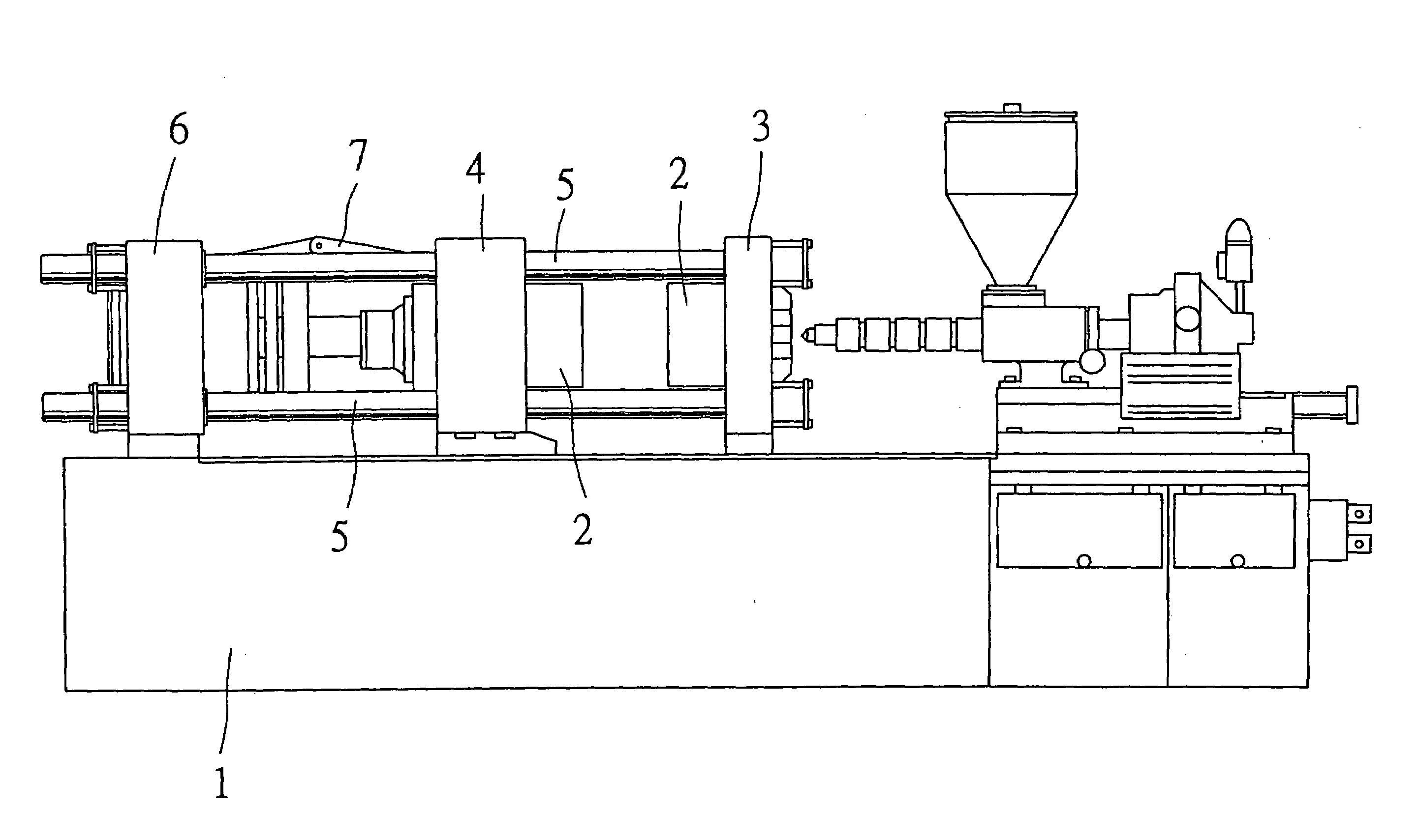
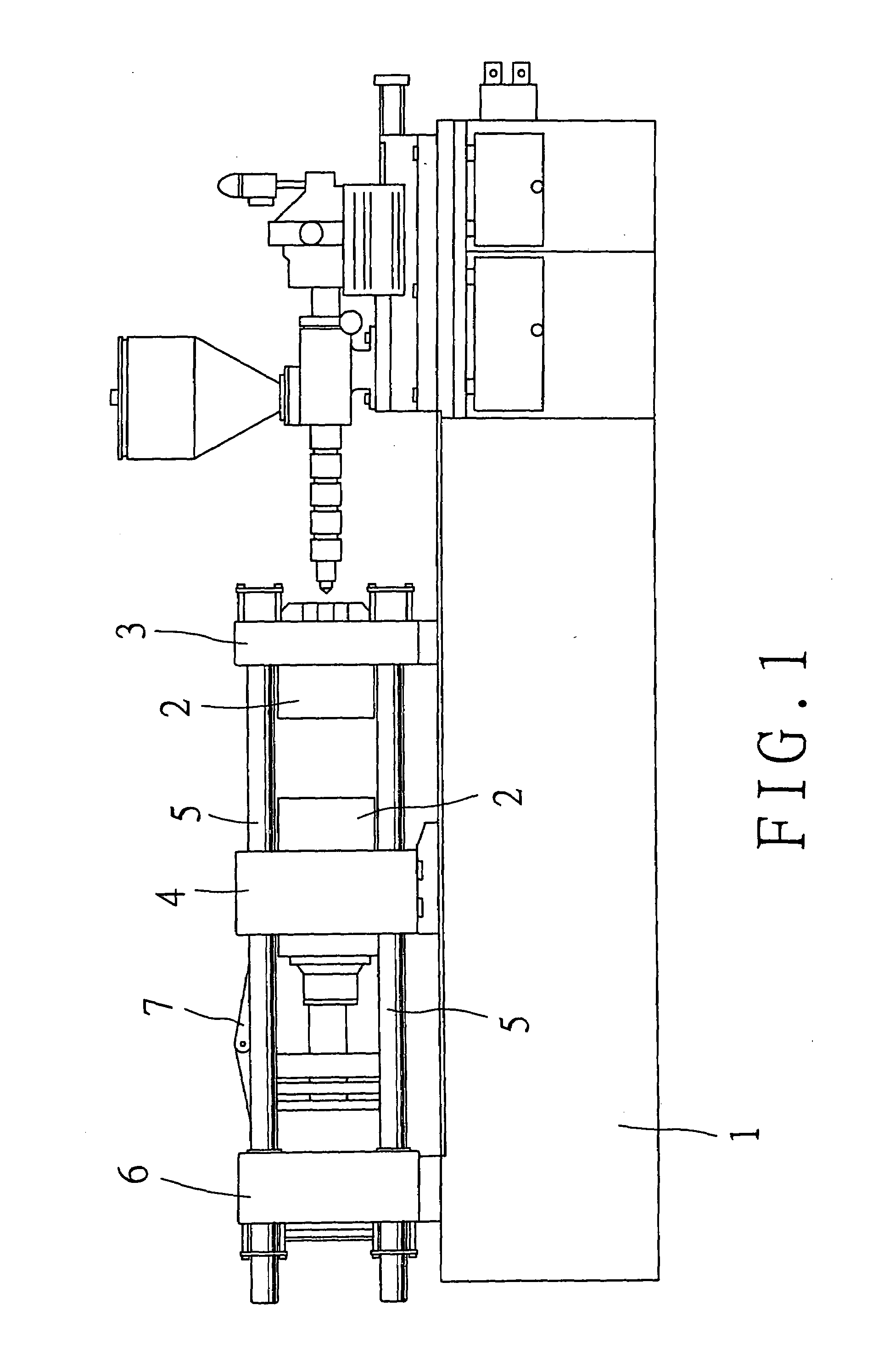
[0022]Referring to FIG. 1, an injection molding machine of the present invention includes a bed 1, a stationary mold holding plate 3, a moving mold holding plate 4, an adjustment plate 6, a driving mechanism 7, two tie bars 5, and a mold 2. The stationary mold holding plate 3, the driving mechanism 7, the moving mold holding plate 4, and the adjustment plate 6 are arranged on the bed 1. The mold comprises a male part, and a female part, which are joined to the stationary and the moving mold holding plates 3 and 4 respectively. The tie bars 5 are passed through the stationary mold holding plate 3, the moving mold holding plate 4, and the adjustment plate 6; thus, the moving mold holding plate 4 can be moved towards / away from the stationary mold holding plate 3 along the tie bars 5 to close / open the mold 2 by means of the driving mechanism 7.

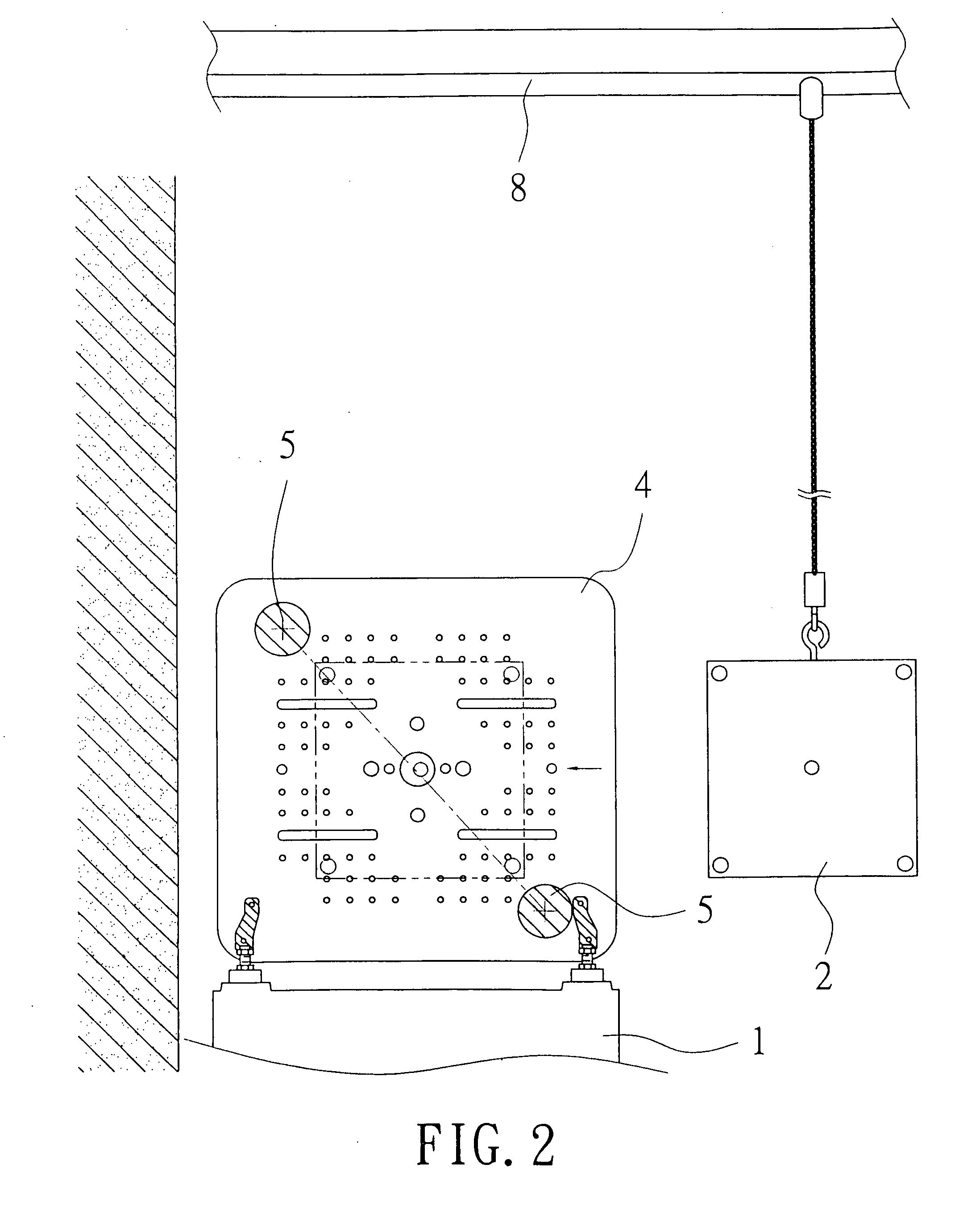
[0023]Referring to FIG. 2, the tie bars 5 are arranged so as to intersect a diagonal line of each of the stationary mold holding plate 3, the mov...


PUM


Abstract

A molding machine includes a bed, a stationary and a moving mold holding plates, an adjustment plate, two tie bars, and a mechanism for driving the moving mold holding plate; both the mold holding plates are arranged on the bed for holding female and male parts of a mold respectively; the adjustment plate is positioned on the bed; the moving mold holding plate is connected to the tie bars so as to be moved along the tie bars when the driving mechanism is actuated; the tie bars pass through all of the plates in such a position as to intersect a diagonal line of each of the plates; to install the mold, male and female parts of the mold can be passed through space next to adjacent vertical and horizontal sides of the holding plates, which don't have a tie bar intervening between them to interfere with installation.

Description

BACKGROUND OF THE INVENTION[0001]1. Field of the Invention[0002]The present invention relates to an injection molding machine, more particularly one, which comprises two tie bars passing through two corners of a stationary and a moving mold holding plates that are on a same diagonal; thus, interference of tie bars with installing / dismounting a mold is prevented.[0003]2. Brief Description of the Prior Art[0004]Plastic products are very common in our daily life, e.g. cups, trays, containers, housings of various electrical appliances, and certain parts of cars and motorbikes. And, a large proportion of household appliances either partially or completely comprise plastic parts, which are usually formed by means of injection molding machines.[0005]The injection molding process with an injection molding machine includes injecting melted plastic materials, which are usually macromolecule polymer, into a mold to shape the melted materials into a product, which is next cooled to become solid...

Claims


Application Information

Patent Timeline
IPC IPC(8): B29C45/00
CPCB29C45/17
Inventor WANG, JUI-HSIANG
Owner HWA CHIN MACHINERY FACTORY
Why Eureka
Try Eureka