Systems and methods for determining touch location

Inactive Publication Date: 2007-06-14
3M INNOVATIVE PROPERTIES CO
View PDF24 Cites 158 Cited by
  • Summary
  • Abstract
  • Description
  • Claims
  • Application Information

AI Technical Summary

Benefits of technology

[0008] According to another aspect of the invention, the arrangement of the first electrodes allows determination of the touch location using

Problems solved by technology
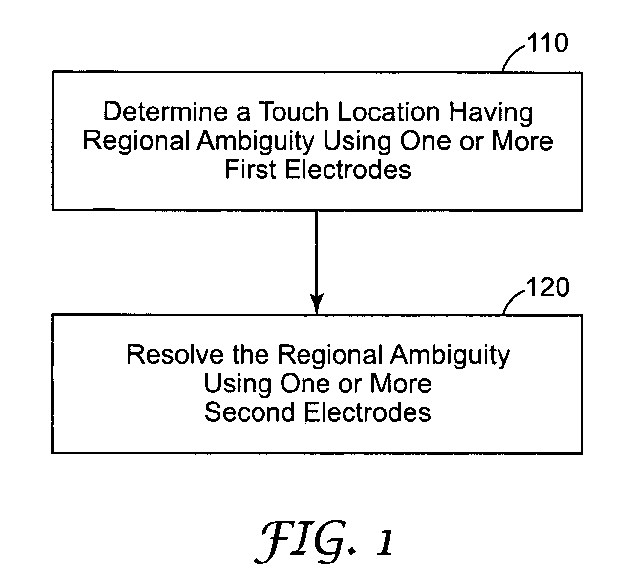
In the past, use of interactive electronic displays has been primarily limite

Method used


Image

  • Systems and methods for determining touch location
  • Systems and methods for determining touch location
  • Systems and methods for determining touch location

Examples


Embodiment Construction

[0026] In the following description of the illustrated embodiments, reference is made to the accompanying drawings that form a part hereof, and in which is shown by way of illustration, various embodiments in which the invention may be practiced. It is to be understood that the embodiments may be utilized and structural changes may be made without departing from the scope of the present invention.

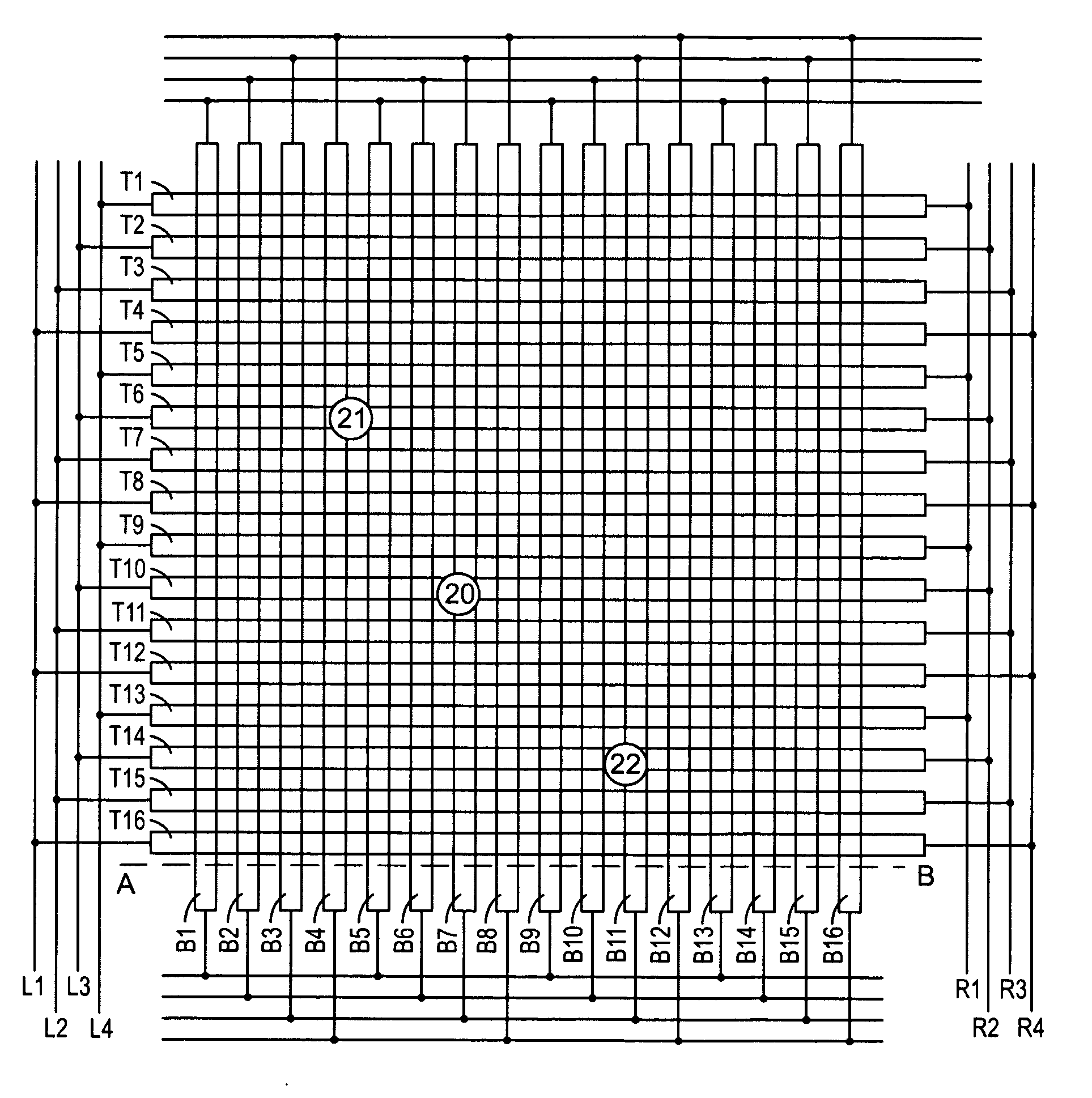
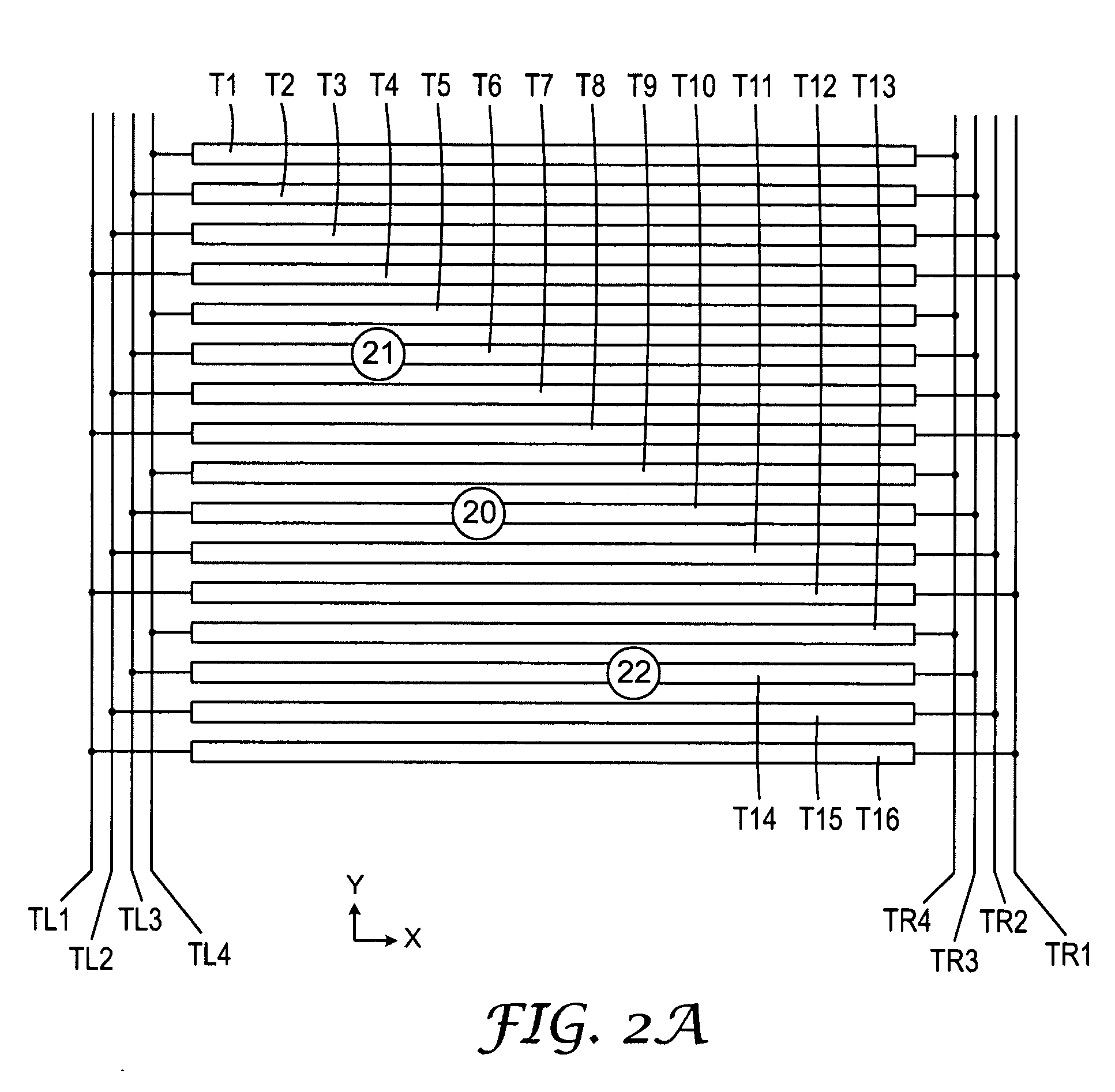
[0027] In various implementations, capacitive touch sensors may include multiple layers of electrodes, such as substantially parallel electrodes, or may include a first layer of electrodes with a planar electrode disposed on a second layer, or may include other electrode configurations. Touch sensing involves detecting changes in electrical signals present at the electrodes in the vicinity of a touch. In some implementations, the touch sensor may use a first layer of parallel electrodes to sense the touch location in the Y-direction and a second layer of parallel electrodes, arranged ortho...


PUM


Abstract

A touch panel includes first and second layers of electrodes. The first layer of electrodes is electrically connected in an arrangement that produces a regional ambiguity in a touch location determined using the first electrodes with respect to a first axis. The second layer of electrodes is configured to resolve the regional ambiguity of the touch location with respect to the first axis. Conversely, the second layer of electrodes may also be connected in an arrangement that creates regional ambiguity in touch location determination of the second layer, and the first layer of electrodes may be configured to resolve that regional ambiguity.

Description

[0001] The present invention relates to methods and systems for determining the location of a touch in proximity with a touch surface. BACKGROUND [0002] Interactive electronic displays are widely used. In the past, use of interactive electronic displays has been primarily limited to computing applications, such as desktop computers and notebook computers. As processing power has become more readily available, electronic displays are being integrated into a wide variety of applications. For example, it is now common to see interactive electronic displays in applications such as teller machines, gaming machines, automotive navigation systems, restaurant management systems, grocery store checkout lines, gas pumps, information kiosks, and hand-held data organizers, to name a few. [0003] Interactive displays often include some form of touch sensitive screen. Integrating touch sensitive panels with visual displays is becoming more common with the emergence of portable multimedia devices. ...

Claims


Application Information

Patent Timeline
IPC IPC(8): G09G5/00
CPCG06F3/0418G06F3/044G06F3/0445G06F3/0446
Inventor MULLIGAN, ROGER C.BADAYE, MASSOUD S.
Owner 3M INNOVATIVE PROPERTIES CO
Why Eureka
Try Eureka