
Radio network system, communication traffic changeover method for the same system, and traffic processing apparatus, line multiplexing apparatus, and host apparatus for the same system

Inactive Publication Date: 2007-06-14
FUJITSU LTD
View PDF9 Cites 13 Cited by
  • Summary
  • Abstract
  • Description
  • Claims
  • Application Information

AI Technical Summary

Benefits of technology

[0014] With the foregoing problems in view, it is an object of the present invention to make it possible to continue communication even when a congestion state occurs in a radio network system due to generation of traffic exceeding the maximum traffic amount which can be processed by the network system (for example, RNCs as traffic processors), without causing a system down or limitation in generation / reception of calls.
[0027] The above-described invention makes it possible to continue communication without causing a system down or call generation / reception limitation even if a congested state occurs in a radio network system. Accordingly, even if a congested state occurs, it is possible to reliably avoid a state where users (mobile terminals) cannot perform communication or make telephone calls.

Problems solved by technology

However, in the network 600 described above with reference to FIG. 10 and FIG. 12, the processing performance of the constituent apparatuses (for example, RNC 200) is limited.
Thus, if traffic exceeding the limit is generated, a limitation in call generating / receiving (for example, no more users are accommodated) can be initiated, or alternatively a system down can be caused.
Thus, simply applying this art to the above-described network 600 (RNCs 200) will not solve the above issue.

Method used


Image

  • Radio network system, communication traffic changeover method for the same system, and traffic processing apparatus, line multiplexing apparatus, and host apparatus for the same system
  • Radio network system, communication traffic changeover method for the same system, and traffic processing apparatus, line multiplexing apparatus, and host apparatus for the same system
  • Radio network system, communication traffic changeover method for the same system, and traffic processing apparatus, line multiplexing apparatus, and host apparatus for the same system

Examples


Embodiment Construction

)

[0041] One preferred embodiment of the present invention will now be described with reference to the accompanying relevant drawings.

[A] One Preferred Embodiment

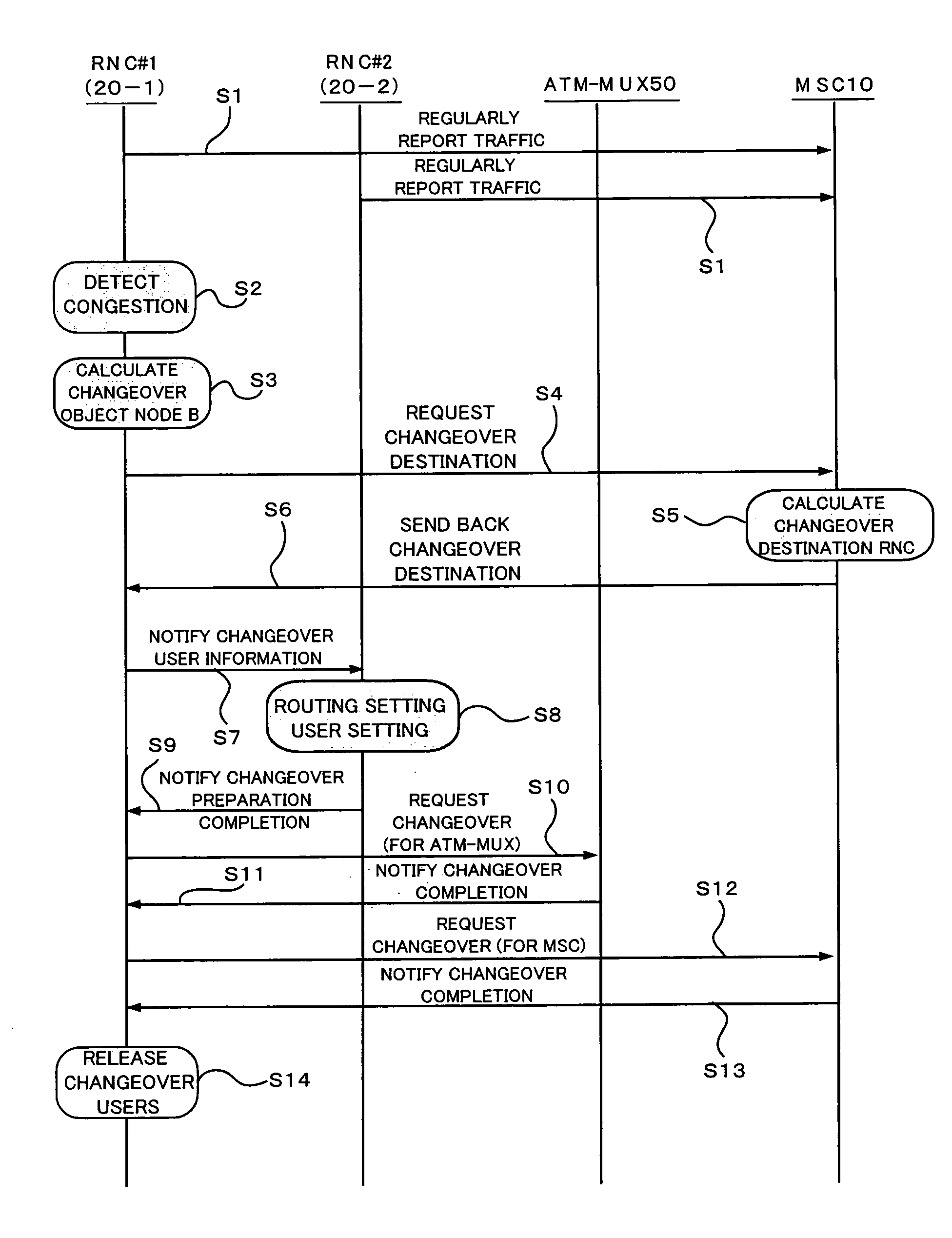
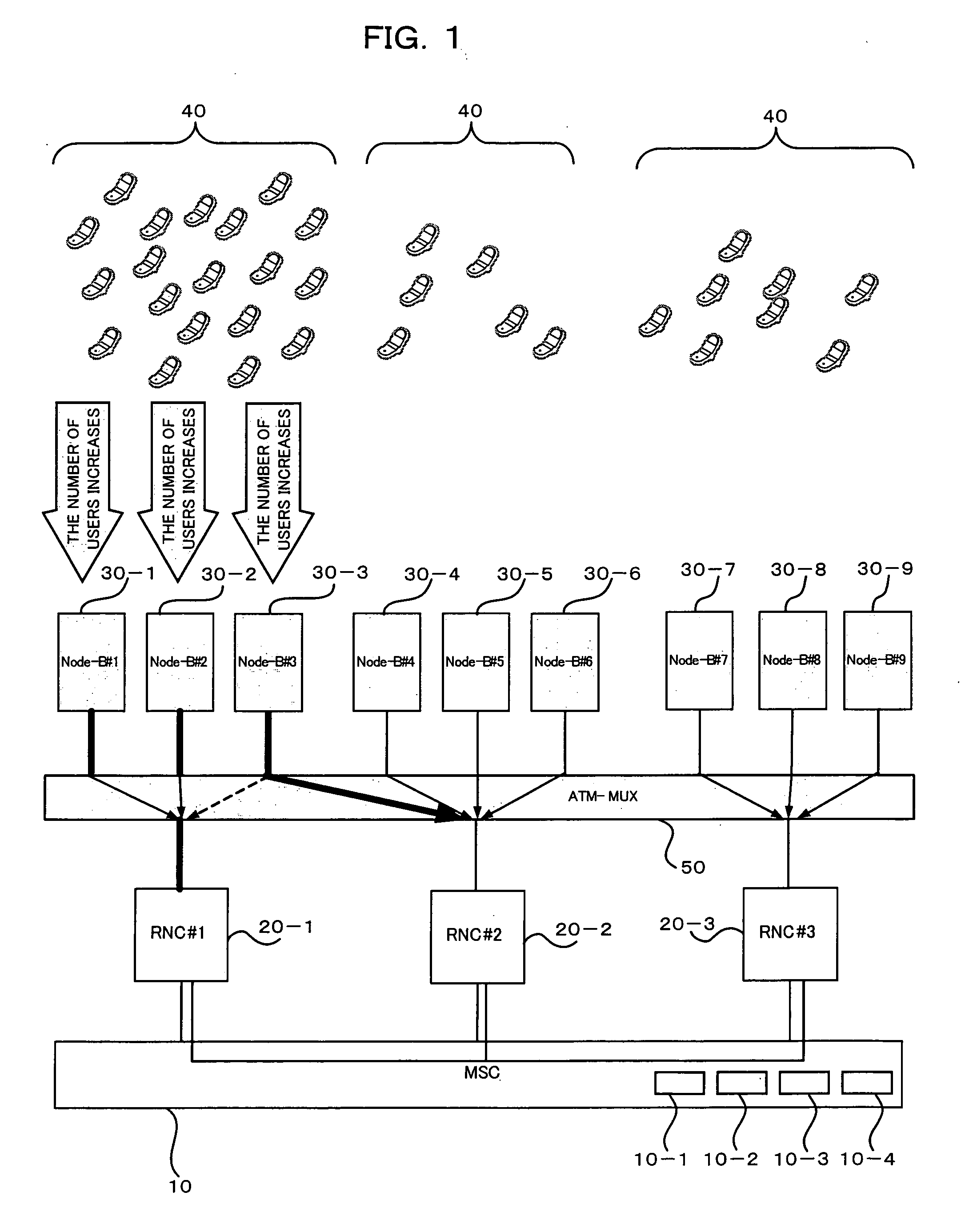
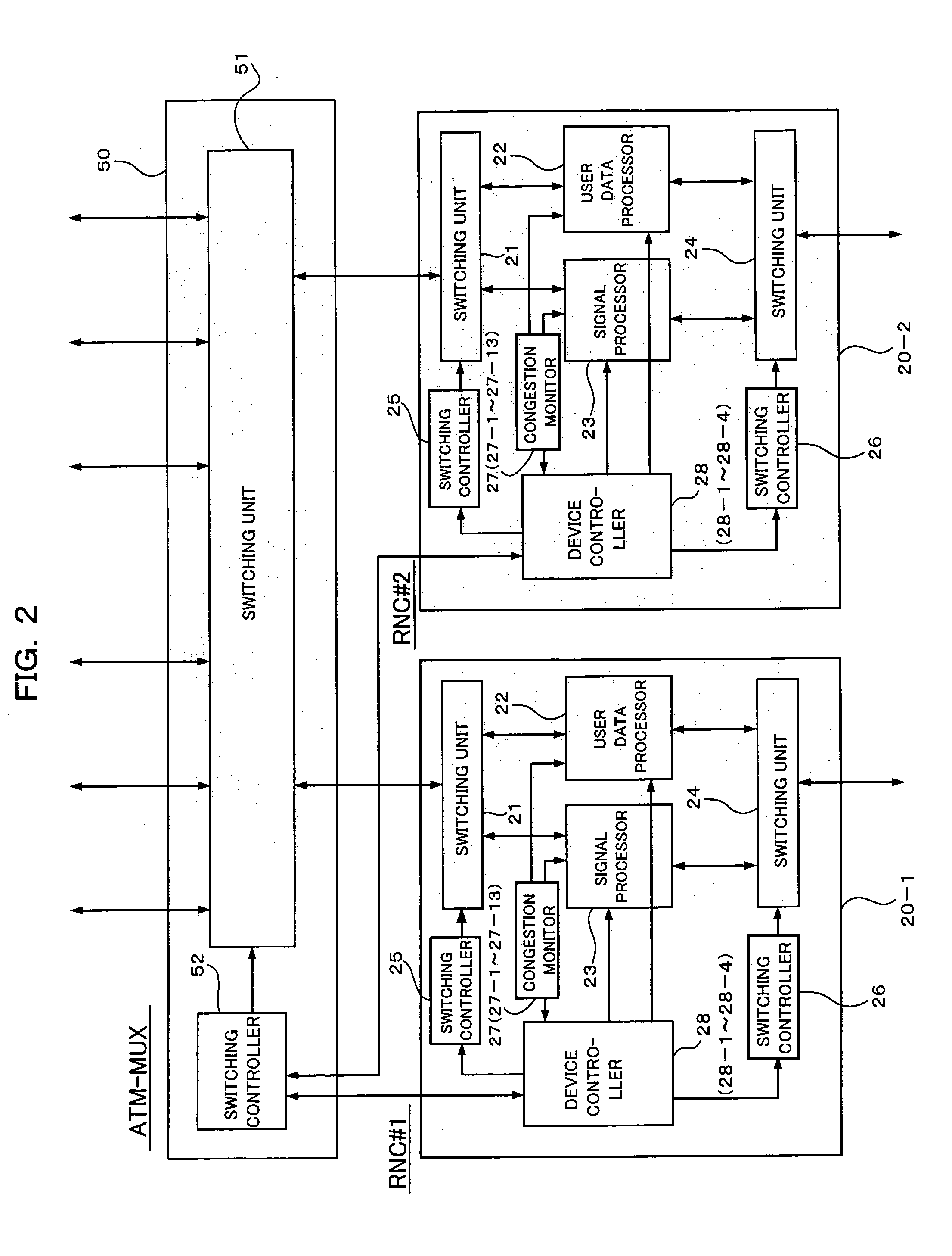
[0042]FIG. 1 is a block diagram showing a construction of a 3GPP (Third Generation Partnership Project) network system according to one preferred embodiment of the present invention. The system of FIG. 1, as in the case of the above-described system [network (UTRAN) 600] includes: a Mobile Switching Center (MSC) 10, which is a constituent of the above-mentioned CN 100 and is a host apparatus; multiple Radio Network Controllers (RNCs) 20-1 through 20-N (in FIG. 1, N=3; apparatus identification Nos. #1, #2, and #3 are given), each of which is a traffic processor communicably connected to the MSC 10 through an “Iu” interface and an “Iur” interface; an ATM multiplexer (ATM-MUX) 50 communicably connected to each of the RNCs 20-i (i=1 through N) through an “Iub” interface; multiple radio base stations (Node-Bs) 30-1 through 30-M...


PUM


Abstract

When a congested state is detected with respect to a traffic processor, the ATM multiplexer performs a line changeover process so that at least a part of communication traffic to be processed by the traffic processing apparatus is processed by another traffic processing apparatus. This arrangement makes it possible to continue communication without causing a system down or call generation / reception limitation, even when traffic exceeds the maximum traffic which can be processed by the radio network system, thereby causing congestion.

Description

CROSS REFERENCE TO RELATED APPLICATIONS [0001] This application is based on and hereby claims priority to Japanese Application No. 2005-354731 filed on Dec. 8, 2005 in Japan, the contents of which are hereby incorporated by reference. BACKGROUND OF THE INVENTION [0002] (1) Field of the Invention: [0003] The present invention relates to a radio network system and a communication traffic changeover method for the same system. The invention also relates to a traffic processor, a line multiplexer, and a host apparatus for use in the same system. The invention relates to an art suitable for use in making it possible to continue communication in a radio network system even when congestion occurs in the network system. [0004] (2) Description of the Related Art: [0005]FIG. 10 is a block diagram showing a network configuration of a 3GPP (Third Generation Partnership Project) network system. The 3GPP system of FIG. 10 normally includes: a host network [Core Network (CN)]100; one or more (two ...

Claims


Application Information

Patent Timeline
IPC IPC(8): H04Q7/00H04L45/586H04W28/08H04W36/22H04W40/34H04W92/24
CPCH04L12/5601H04L47/10H04L47/122H04L47/14H04L2012/5636H04L2012/5672H04L2012/568H04W36/22H04W28/0247H04W28/0289H04W8/04
Inventor HARA, MASAYUKI
Owner FUJITSU LTD
Learn More