Wide-bandwidth mode-locked laser

a mode-locked laser and wide-bandwidth technology, applied in the direction of laser details, laser optical resonator construction, optical resonator shape and construction, etc., can solve the problem of relatively narrow wavelength range (spectral bandwidth) provided by such lasers, and achieve the effect of wide combined gain spectrum

Inactive Publication Date: 2007-06-14
WSOU INVESTMENTS LLC +1
View PDF14 Cites 37 Cited by
  • Summary
  • Abstract
  • Description
  • Claims
  • Application Information

AI Technical Summary

Benefits of technology

[0005] Problems in the prior art are addressed, in accordance with the principles of the present invention, by a mode-locked laser that has an optical cavity containing (i) multiple optical amplifiers, each dedicated to a respective spectral portion of an optical signal generated by the laser, (ii) means for managing intra-cavity dispersion effects, and (iii) a loss-modulating element. The optical cavity dispersion effects can be managed by utilizing a separate intra-cavity phase tuner for each such spectral portion and / or by having appropriately configured waveguides corresponding to different spectral portions. Advantageously, a relatively wide combined gain spectrum provided by the optical amplifiers and the intra-cavity dispersion compensation provided by the phase tuners and / or waveguides enable this laser to realize a mode-locking regime that results in the emission of an optical pulse train having a relatively wide (e.g., octave-spanning) frequency spectrum.

Problems solved by technology

However, a general problem with prior-art semiconductor ML lasers is that a typical range of wavelengths (spectral bandwidth) provided by such lasers is relatively narrow, e.g., about 20 nm.

Method used


Image

  • Wide-bandwidth mode-locked laser
  • Wide-bandwidth mode-locked laser
  • Wide-bandwidth mode-locked laser

Examples


Embodiment Construction

[0010] Reference herein to “one embodiment” or “an embodiment” means that a particular feature, structure, or characteristic described in connection with the embodiment can be included in at least one embodiment of the invention. The appearances of the phrase “in one embodiment” in various places in the specification are not necessarily all referring to the same embodiment, nor are separate or alternative embodiments mutually exclusive of other embodiments.

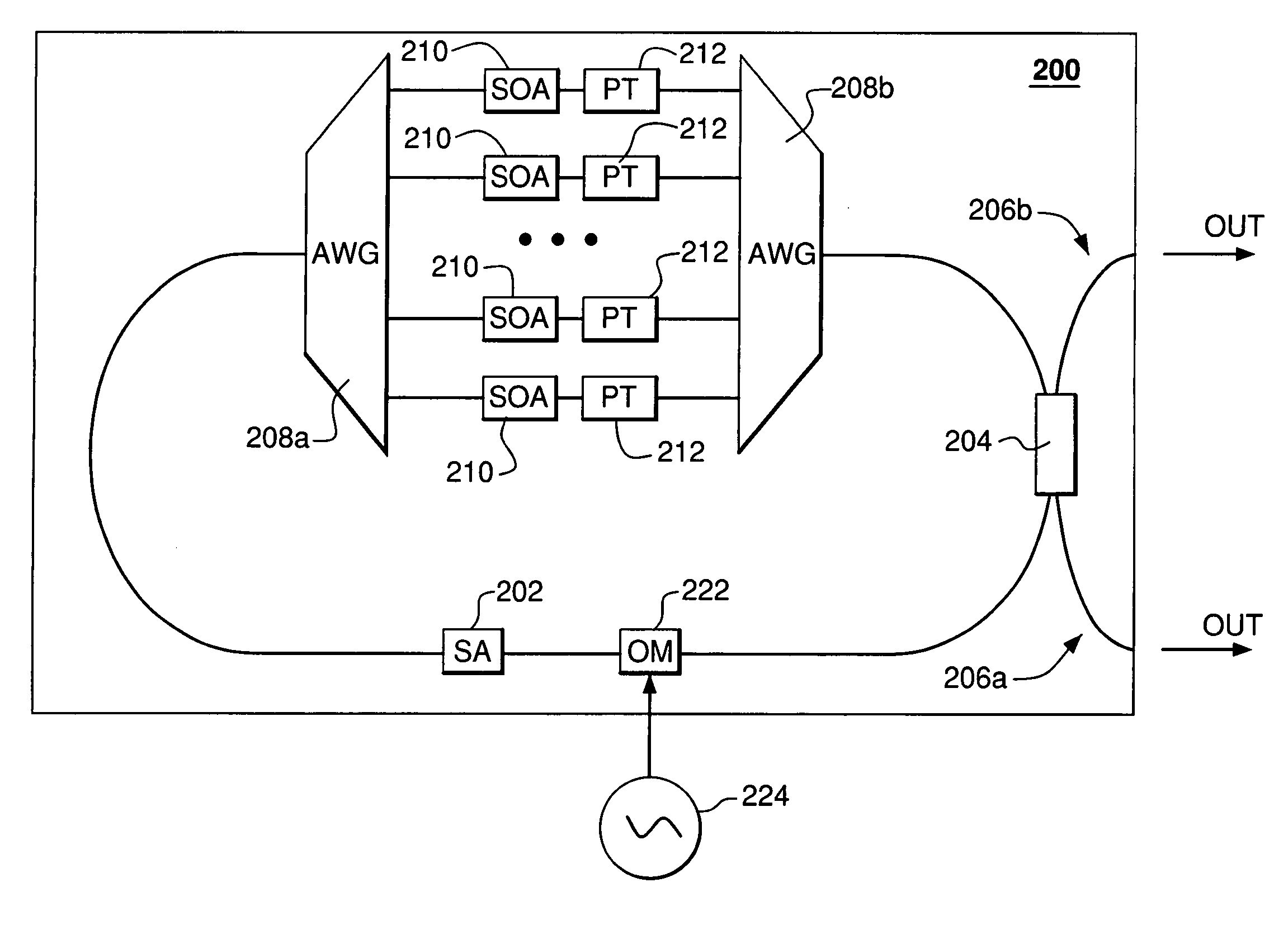
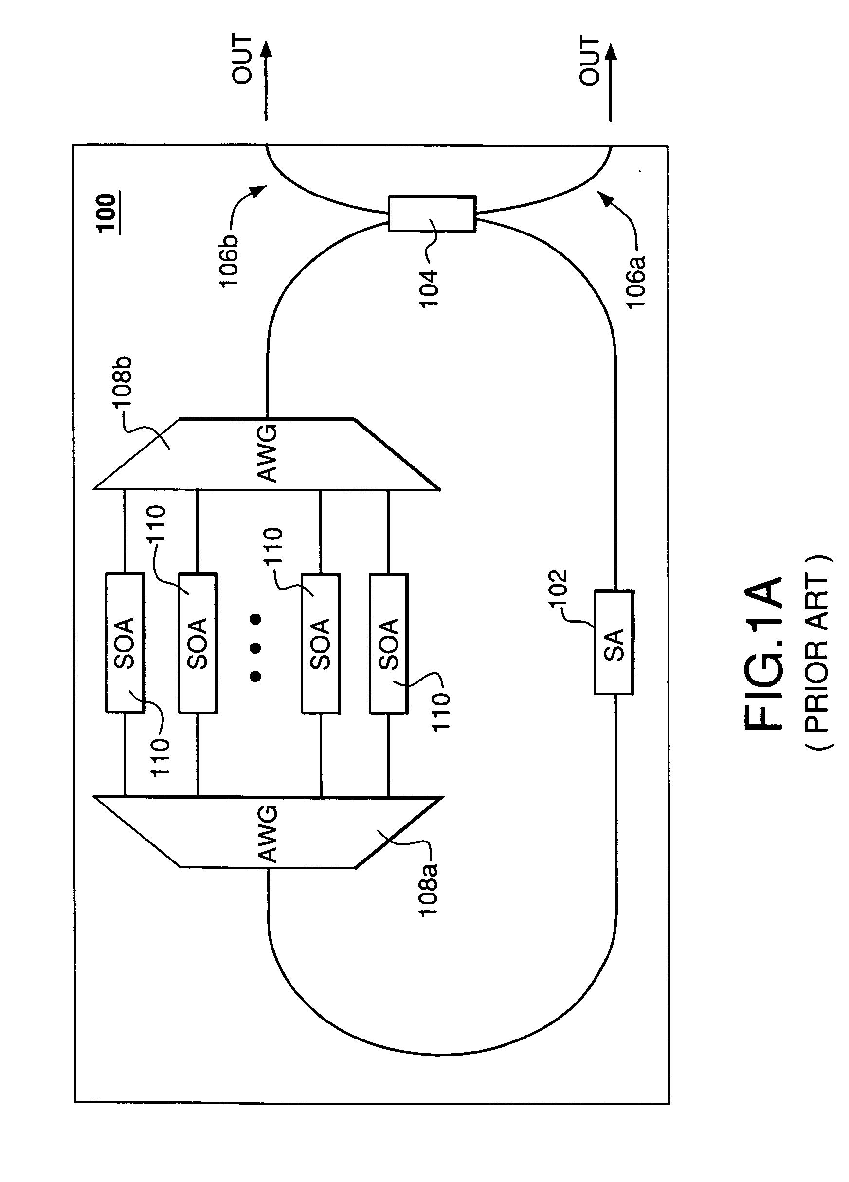
[0011] Mode locking is a method of obtaining ultra-short optical pulses from a laser that is called a mode-locked (ML) laser. The optical cavity of an ML laser contains an active modulating element (e.g., an optical modulator) or a nonlinear passive modulating element (e.g., a saturable absorber) or both, which causes formation of one or more ultra-short pulses circulating in the laser cavity. Each time a circulating pulse hits the output coupler (e.g., a partially transparent mirror), light is emitted from the laser, thereby pro...


PUM


Abstract

A mode-locked laser that has an optical cavity containing multiple optical amplifiers, each dedicated to a respective spectral portion of an optical signal generated by the laser, wherein the dispersion effects are managed by utilizing a separate intra-cavity phase tuner for each such spectral portion and/or by having appropriately configured waveguides corresponding to different spectral portions. Advantageously, a relatively wide combined gain spectrum provided by the optical amplifiers and the intra-cavity dispersion compensation provided by the phase tuners and/or waveguides enable this laser to realize a mode-locking regime that results in the emission of an optical pulse train having a relatively wide frequency spectrum. In one embodiment, the optical cavity of the mode-locked laser has a perfectly spectrally sampled arrayed waveguide grating (AWG) that is configured to divide the optical signal into the spectral portions and apply these portions to the respective waveguides, optical amplifiers, and phase tuners.

Description

BACKGROUND OF THE INVENTION [0001] 1. Field of the Invention [0002] The present invention relates to optical communication equipment and, more specifically, to optical sources used in optical communication systems. [0003] 2. Description of the Related Art [0004] Modern optical communication systems transmit information between communication nodes using wavelength division multiplexed (WDM) signals. The generation of WDM signals in such systems relies on light sources capable of producing electromagnetic radiation at appropriate multiple wavelengths (frequencies). One such light source is a semiconductor mode-locked (ML) laser, which owes its utility to its relatively small size, high power, low noise, and low cost. However, a general problem with prior-art semiconductor ML lasers is that a typical range of wavelengths (spectral bandwidth) provided by such lasers is relatively narrow, e.g., about 20 nm. SUMMARY OF THE INVENTION [0005] Problems in the prior art are addressed, in accor...

Claims


Application Information

Patent Timeline
Patent Type & Authority Applications(United States)
IPC IPC(8): H01S3/098H01S3/13H01S3/08
CPCH01S3/083H01S3/1109H01S3/1115H01S5/026H01S5/0268H01S5/0657H01S5/1071H01S5/4062H01S5/4068H01S5/4087H01S3/00H01S5/10
Inventor DOERR, CHRISTOPHER RICHARD
Owner WSOU INVESTMENTS LLC
Why Eureka
Try Eureka