Radio communications device and radio communications controlling method

Inactive Publication Date: 2007-06-14
KYOCERA CORP
View PDF7 Cites 19 Cited by
  • Summary
  • Abstract
  • Description
  • Claims
  • Application Information

AI Technical Summary

Benefits of technology

[0015] The present invention has been made in view of this problem. It is an object of the present invention to provide a radio communications device and a radio communications controlling method capable of ensuring both the delayed wave resistance and the fading resistance in good balance.
[0017] According to this aspect, the radio communications device properly changes not only a length of the guard interval but also the subcarrier interval to those of a different mode depending on the length of the delay time. For this reason, the radio communications device can ensure both the delayed wave resistance and the fading resistance in good balance even in a situation where a communication environment between the communications device and a communication counterpart device changes.
[0021] According to the aspects of the present invention, it is possible to ensure both the delayed wave resistance and the fading resistance in good balance.

Problems solved by technology

However, this radio communications device is merely configured to change the GI length depending on the length of the delay time, and is therefore incapable of ensuring both the delayed wave resistance and the fading resistance in good balance.
Specifically, in a situation where a communication environment (such as an urban area or a hilly area) between the radio communications device and a communication counterpart device (such as a mobile device) changes, the radio communications device cannot sufficiently ensure the delayed wave resistance and the fading resistance depending on the communication environment.

Method used


Image

  • Radio communications device and radio communications controlling method
  • Radio communications device and radio communications controlling method
  • Radio communications device and radio communications controlling method

Examples


first modified example

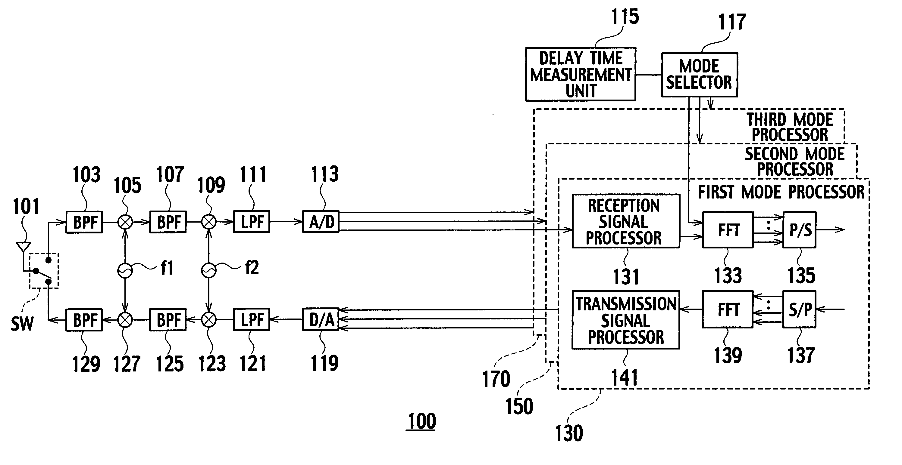
[0069] In the above-described embodiment, the first mode processor 130, the second mode processor 150, or the third mode processor 170 allocates subchannels formed of the plurality of subcarriers to a single communication counterpart device (such as the terminal device 200-1) (see FIG. 4).

[0070] In this modified example, the first mode processor 130, the second mode processor 150, or the third mode processor 170 is configured to allocate subchannels respectively to different communication counterpart devices for each of the time slots obtained by dividing a frame to be repeated at a predetermined unit cycle (such as 2.5 ms) (see FIGS. 4A to 4C and FIG. 7A to 7C).

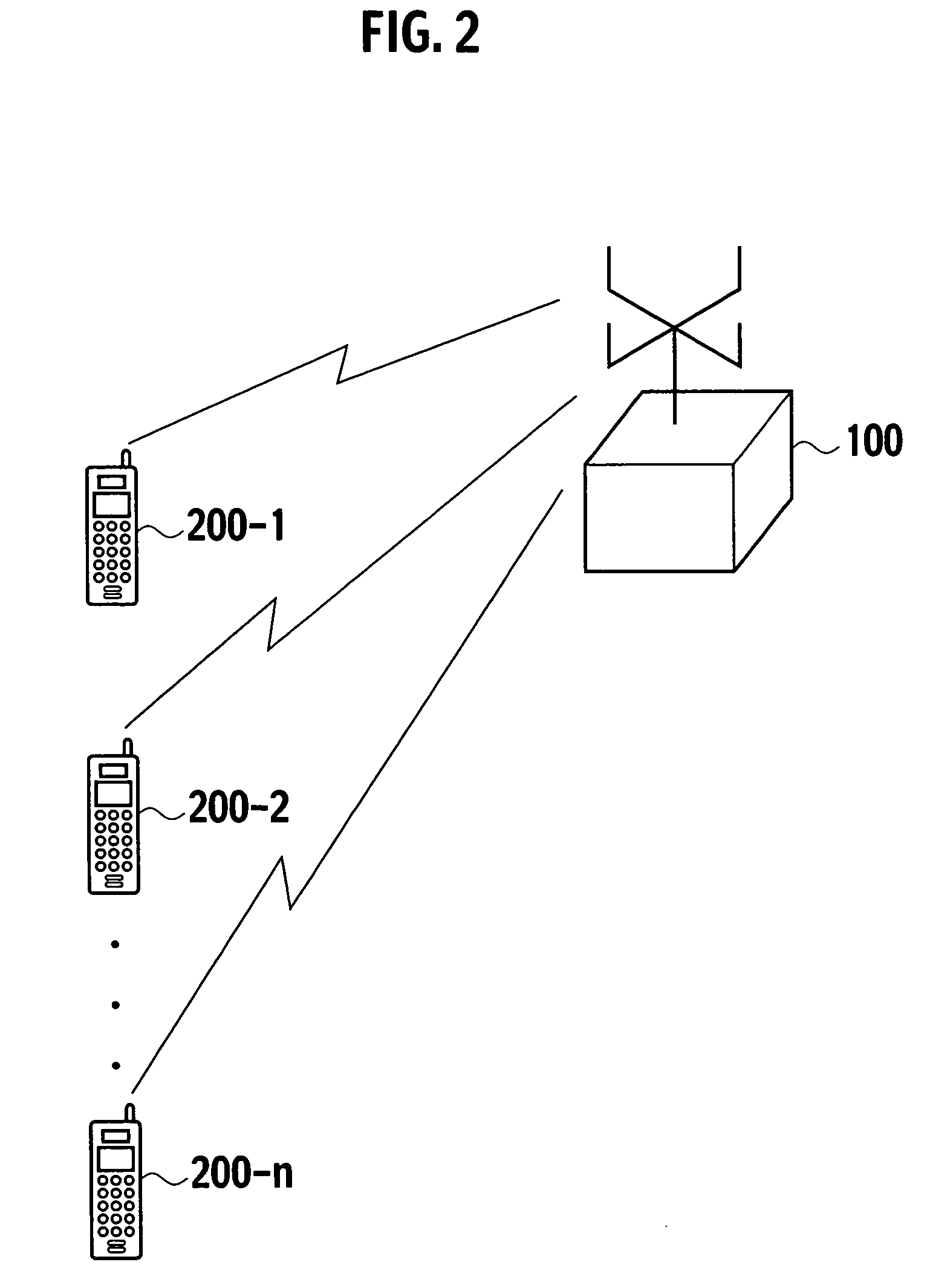
[0071] For example, as shown in FIG. 4A and FIG. 7A, the first mode is applied to two subcarriers in a predetermined frequency band. The subchannels each composed of the single subcarrier are allocated to the terminal devices 200-1 and 200-2, respectively.

[0072] As shown in FIG. 4B and FIG. 7B, the second mode is applied ...

second modified example

[0075] The mode selector 117 may select any mode on the time slot basis. Further, the mode selector 117 may select any mode (the mode in accordance with the number of subchannels) on the time slot basis in a case where a plurality of subchannels is allocated to a single communication counterpart device.

[0076] For example, in a case where two subchannels are respectively allocated to the terminal devices 200-1 and 200-2 in a certain time slot as shown in FIG. 8, the radio base station 100 selects the first mode while targeting the two subchannels.

[0077] In this way, the radio base station 100 can apply the GI length and the subcarrier interval properly for each of the time slots. Accordingly, the radio base station 100 can ensure both the delayed wave resistance and the fading resistance in good balance for each of the time slots.

third modified example

[0078] In a case where a plurality of subchannels are allocated to a single communication counterpart device, the mode selector 117 may change the subcarrier interval in accordance with the selected mode with a wider subcarrier interval than the subcarrier interval.

[0079] The following explanation will be based on the assumption that the second mode is selected. However, the present invention is not limited only to this selection and it is by all means possible to select the first mode or the third mode instead.

[0080]FIG. 9A shows contents of the transmission symbol in accordance with the second mode. FIG. 9B shows contents of the transmission symbol in accordance with a second mode-expand, which is derived from the original second mode.

[0081] For example, in a case where the plurality of subchannels are allocated to the single terminal device, the mode selector 117 selects the second mode-expand having the wider subcarrier interval (such as 96 kHz as shown in FIG. 9A) than the s...


PUM


Abstract

The present invention aims at ensuring both delayed wave resistance and fading resistance in good balance. A delay time measuring unit measures delay time determined based on a time point of a subcarrier out of a plurality of subcarriers arriving first and a time point of another subcarrier arriving through multipath at each predetermined time interval. A mode selector selects a mode out of a plurality of modes formed as combinations of a subcarrier interval representing an interval between mutually adjacent subcarriers out of the plurality of subcarriers and the guard interval depending on a length of the delay time. A first mode processor, a second mode processor or a third mode processor executes transmission and reception of a transmission signal by use of the selected mode.

Description

CROSS-REFERENCE TO RELATED APPLICATIONS [0001] This application is based upon and claims the benefit of priority from the prior Japanese Patent Applications No. P2005-355463, filed on Dec. 8, 2005; the entire contents of which are incorporated herein by reference. BACKGROUND OF THE INVENTION [0002] 1. Field of the Invention [0003] The present invention relates to a radio communications device and a radio communications controlling method, which are configured to execute transmission and reception of a transmission signal formed by multiplexing a transmission symbol containing a guard interval by use of at least a part of a plurality of subcarriers. [0004] 2. Description of the Related Art [0005] Conventionally, data transmission is executed by a transmission symbol as a unit in a system using the orthogonal frequency division multiplexing technique (OFDM). Each transmission symbol includes a guard interval. The guard interval is a certain time interval to be inserted to reduce an in...

Claims


Application Information

Patent Timeline
IPC IPC(8): H04K1/10
CPCH04L27/2605H04L27/2608H04L5/0044
Inventor IWAMI, MASASHI
Owner KYOCERA CORP
Why Eureka
Try Eureka