Hinge assembly for flat display monitor

a flat display monitor and hinge assembly technology, applied in the field of hinge assemblies, can solve the problems of limiting the total volume and final weight of the crt, user fatigue, and inconvenient operation of the hinge assembly by users

Inactive Publication Date: 2007-06-21
HON HAI PRECISION IND CO LTD
View PDF24 Cites 7 Cited by
  • Summary
  • Abstract
  • Description
  • Claims
  • Application Information

AI Technical Summary

Benefits of technology

[0005]In one embodiment thereof, a hinge assembly for use in a flat display monitor includes a support seat, a base seat and a pivot mechanism. The support seat has a cutout defined by two opposed side surfaces. The base seat includes a resisting member disposed thereon. The pivot mechanism rotatably connects the support seat to the base seat. A resisting member on the base seat is movable in the cutout of the support seat upon rotating of the support seat relative to the base seat. The two side surfaces are configured to engage with the resisting member when the support seat rotates relative to the base seat in a manner so as to prevent the resisting member from moving further to limit a rotation angle between the support seat and the base seat.

Problems solved by technology

This configuration is a huge factor in limiting the total volume and final weight of the CRT monitor.
In addition, the CRT monitor carries a huge problem in that a user is easily fatigued when looking at the CRT monitor over several hours due to its low image quality.
It is this problem alone that many people switched to using a flat screen display monitor, e.g., liquid crystal display (LCD) monitor, from the conventional CRT monitors.
However, in use, it needs to use great efforts to rotate the hinge assembly, since a greater force is exerted thereon.
As a result, it is inconvenient for a user to operate the hinge assembly.

Method used


Image

  • Hinge assembly for flat display monitor
  • Hinge assembly for flat display monitor
  • Hinge assembly for flat display monitor

Examples


Embodiment Construction

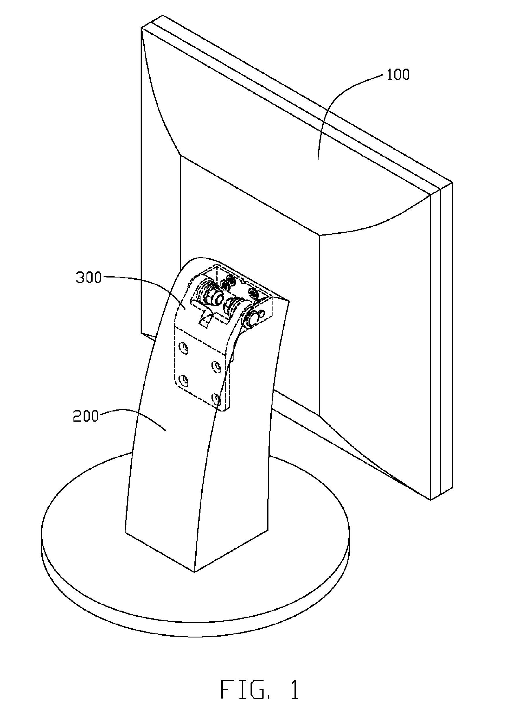
[0013]Referring to drawings in detail, FIG. 1 shows a flat display monitor employing a hinge assembly 300 in accordance with one embodiment of the present application. The flat display monitor is taken here as an exemplary application, for the purposes of describing details of the hinge assembly 300. It is to be understood, however, that the hinge assembly 300 could be advantageously used in other environments (e.g. cabinet doors). As such, although providing particularly advantages when used in flat display monitors, the hinge assembly 300 should not be considered limited in scope solely to an intended use environment of flats display monitors. The flat display monitor includes a display unit 100 and a support body 200. The hinge assembly 300 connects the display unit 100 to the support body 200 such that the display unit 100 can be pivoted relative to the support body 200.

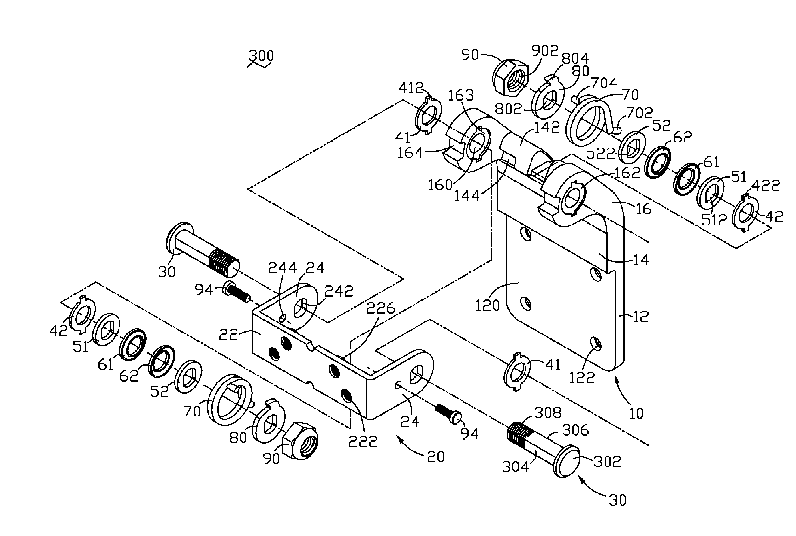
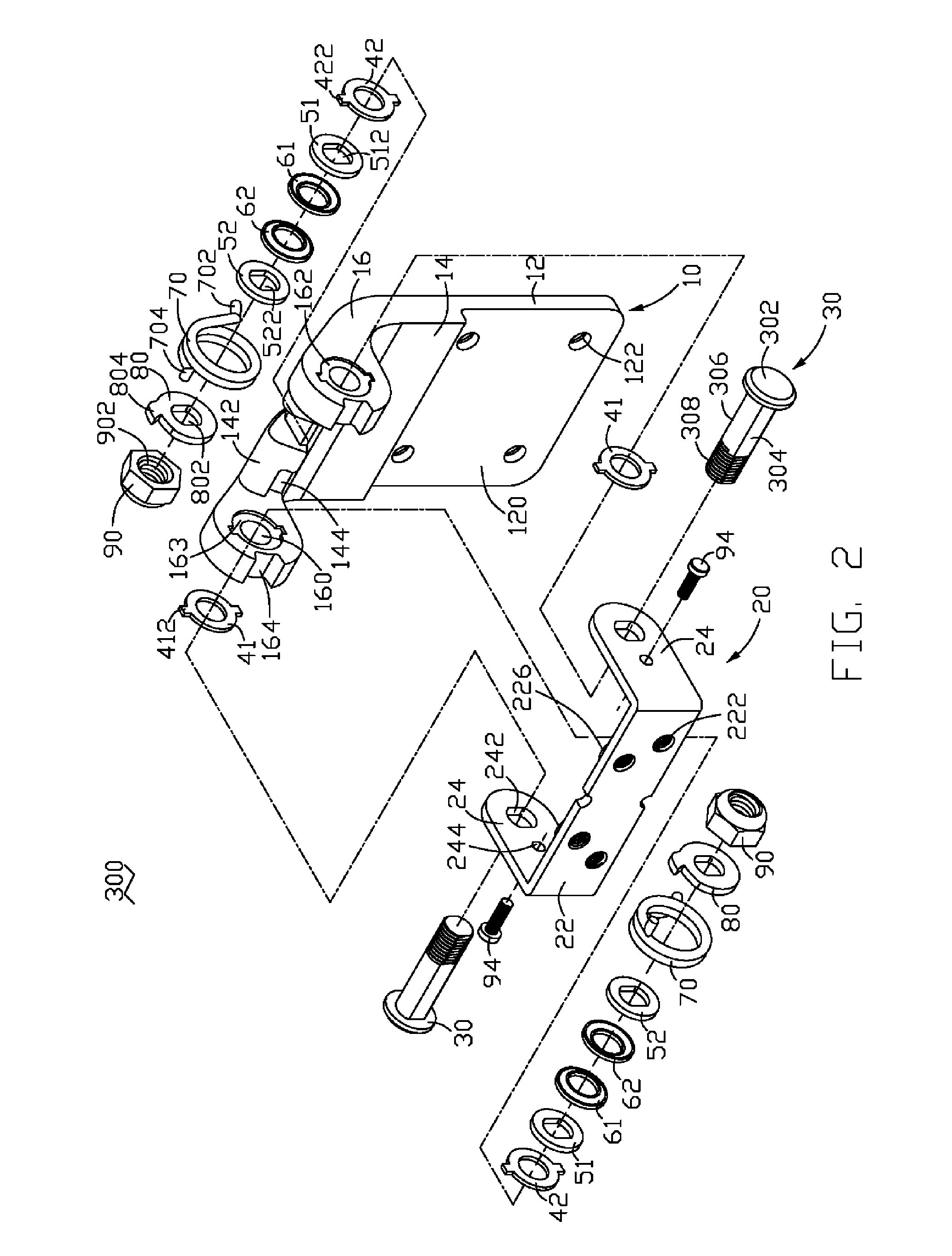
[0014]Referring to FIG. 2, the hinge assembly 300 includes a support seat 10, a base seat 20, and two pivot me...


PUM


Abstract

A hinge assembly (300) for use in a flat display monitor includes a support seat (10), a base seat (20) and a pivot mechanism. The support seat has a cutout (164) defined by two opposed side surfaces. The base seat includes a resisting member disposed thereon. The pivot mechanism rotatably connects the support seat to the base seat. A resisting member (94) on the base seat is movable in the cutout of the support seat upon rotating of the support seat relative to the base seat. The two side surfaces are configured to engage with the resisting member when the support seat rotates relative to the base seat in a manner so as to prevent the resisting member from moving further to limit a rotation angle between the support seat and the base seat.

Description

FIELD OF THE INVENTION[0001]The present invention generally relates to hinge assemblies and, particularly, to a hinge assembly for a flat display monitor.DISCUSSION OF THE RELATED ART[0002]With the widespread use and the variety of computers available, display devices configured for such a variety of computers also come in a wide range of sizes, shapes, and weight. In general, a typical cathode-ray tube (CRT) monitor includes a display panel for displaying an image, a vacuum tube coupled to the rear of the display panel, and an electron gun coupled to the rear of the vacuum tube. This configuration is a huge factor in limiting the total volume and final weight of the CRT monitor. In addition, the CRT monitor carries a huge problem in that a user is easily fatigued when looking at the CRT monitor over several hours due to its low image quality. It is this problem alone that many people switched to using a flat screen display monitor, e.g., liquid crystal display (LCD) monitor, from t...

Claims


Application Information

Patent Timeline
Patent Type & Authority Applications(United States)
IPC IPC(8): E05D11/08
CPCE05D11/06E05D11/087Y10T16/540345F16M11/10F16M2200/041E05Y2900/606
Inventor HU, AN-KUI
Owner HON HAI PRECISION IND CO LTD
Why Eureka
Try Eureka