Magnetized pulsar ring

Inactive Publication Date: 2007-06-21
JTEKT CORP
View PDF13 Cites 8 Cited by
  • Summary
  • Abstract
  • Description
  • Claims
  • Application Information

AI Technical Summary

Benefits of technology

[0033] Further, the relative rotation preventing concave portion or convex portion may be provided in the side surface of the flange portion. In this case, it is possible to do away with the come-off preventing portion which is provided in the outer periphery of the magnetized body and is engaged with the outer peripheral portion of the flange portion, or it is possible to set this. In accordance with the rolling bearing apparatus with sensor shown in FIG. 15, since the magnetized body is attached to one side surface, and the other side surface can be used as a sliding surface of an elastic seal, it is hard to enlarge the thickness of the come-off preventing portion engaging with the outer peripheral portion of the flange portion. Accordingly, the come-off preventing portion of the magnetized body becomes relatively weak for the thermal shock. Since the relative rotation preventing concave portion or convex portion can improve an adhesive property between the magnetized body and the support member, the come-off preventing portion may be omitted for the rolling bearing with sensor. In the case that the come-off preventing portion is provided, it is possible to securely execute both of the prevention of the relative rotation and the come-off prevention, so that an extremely high reliability can be obtained.
[0034] Further, the magnetized body may be additionally added with a linear expansion coefficient adjusting material for making a linear expansion coefficient of the magnetized body close to a linear expansion coefficient of

Problems solved by technology

In the magnetized pulsar ring mentioned above, there is a case that the magnetized body formed by magnetizing magnetic powders having a rubber as a binder is damaged by a foreign material or the like.
However

Method used


Image

  • Magnetized pulsar ring
  • Magnetized pulsar ring
  • Magnetized pulsar ring

Examples


first embodiment

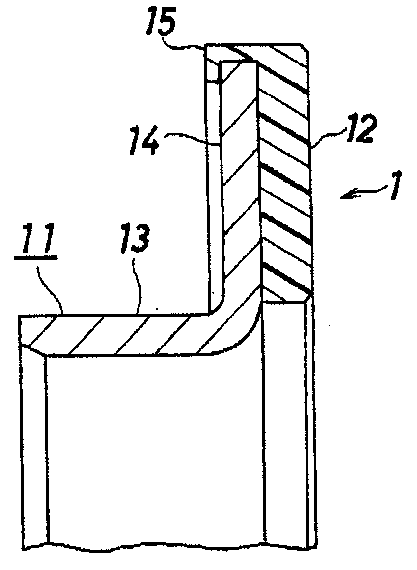
[0053]FIG. 1 shows a magnetized pulsar ring in accordance with this invention.

[0054] In FIG. 1, a magnetized pulsar ring 1 is constituted by a support member 11 fixed to an inner ring, and a magnetized body 12 provided in a support member 11.

[0055] The support member 11 is constituted by a cylinder portion 13 fitted and fixed to an outer periphery of the inner ring, and an outward flange portion 14 provided in a right end portion of the cylinder portion 13.

[0056] The magnetized body 12 is constituted by a resin bonded magnet, and is fixed over an almost entire periphery of a right surface of the flange portion 14 of the support member 11 in accordance with an integral injection molding.

[0057] An outer periphery of the magnetized body 12 is provided with a come-off preventing portion 15 having an inverted-L shaped cross section and engaging with an outer peripheral portion of the flange portion 14, and the magnetized body 12 is prevented from coming off from the support member 11 ...

second embodiment

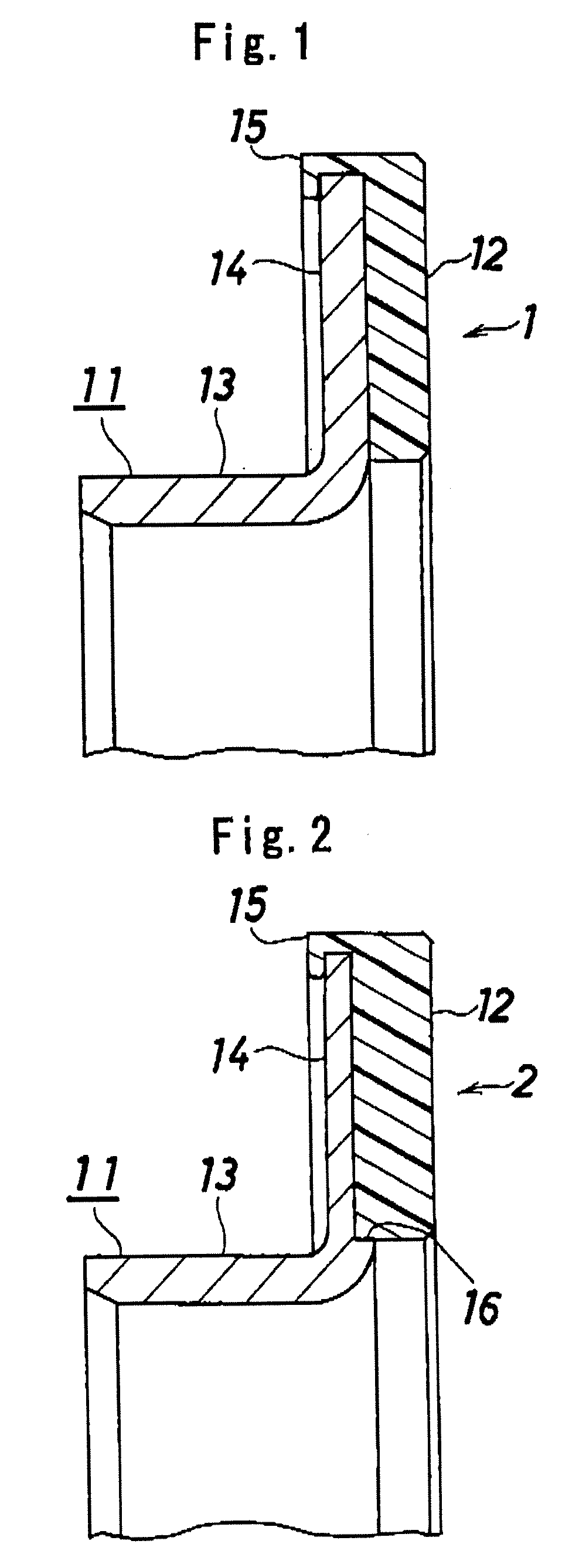
[0059]FIG. 2 shows the magnetized pulsar ring in accordance with this invention.

[0060] In this drawing, a magnetized pulsar ring 2 is constituted by a support member 11 fixed to an inner ring, and a magnetized body 12 provided in a support member 11.

[0061] The support member 11 is constituted by a cylinder portion 13 fitted and fixed to an outer periphery of the inner ring, and an outward flange portion 14 provided in a right end portion of the cylinder portion 13.

[0062] The magnetized body 12 is constituted by a resin bonded magnet, and is fixed over an almost entire periphery of a right surface of the flange portion 14 of the support member 11 in accordance with an integral injection molding.

[0063] An outer periphery of the magnetized body 12 is provided with a come-off preventing portion 15 having an inverted-L shaped cross section and engaging with an outer peripheral portion of the flange portion 14, and the magnetized body 12 is prevented from coming off from the support me...

third embodiment

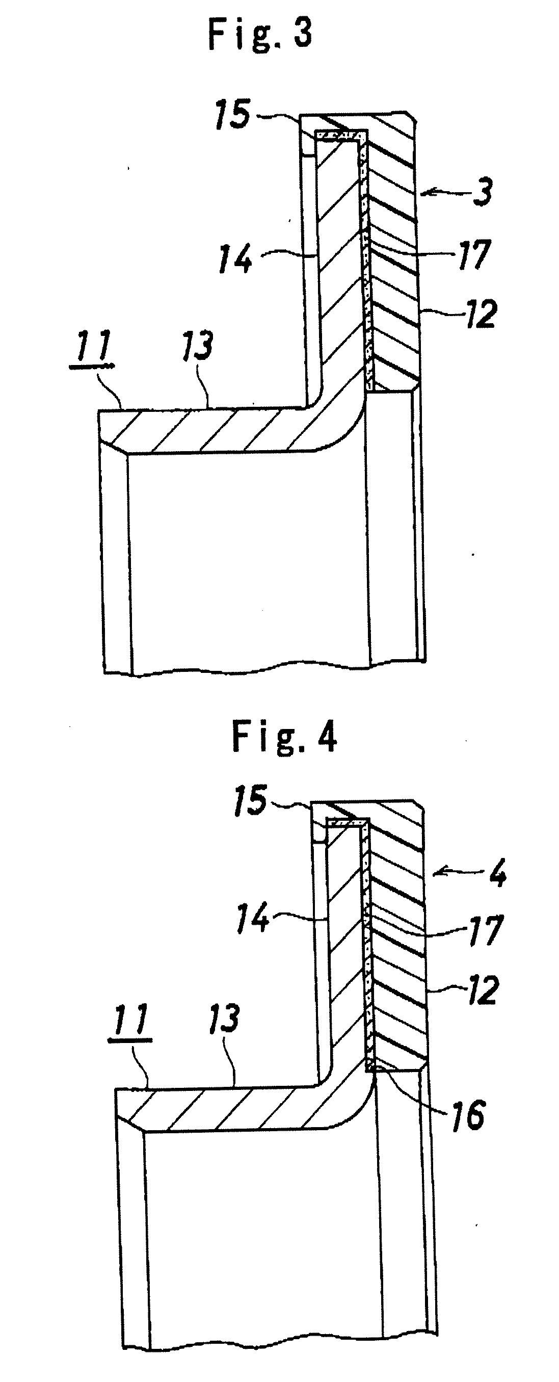
[0067]FIG. 3 shows the magnetized pulsar ring in accordance with this invention.

[0068] In FIG. 3, a magnetized pulsar ring 3 is constituted by a support member 11 fixed to an inner ring, and a magnetized body 12 provided in a support member 11.

[0069] The support member 11 is constituted by a cylinder portion 13 fitted and fixed to an outer periphery of the inner ring, and an outward flange portion 14 provided in a right end portion of the cylinder portion 13,

[0070] The magnetized body 12 is constituted by a resin bonded magnet, and is fixed over an almost entire periphery of a right surface of the flange portion 14 of the support member 11 in accordance with an integral injection molding.

[0071] An outer periphery of the magnetized body 12 is provided with a come-off preventing portion 15 hating an inverted-L shaped cross section and engaging with an outer peripheral portion of the flange portion 14, and the magnetized body 12 is prevented from coming off from the support member 1...


PUM


Abstract

A magnetized body (12) is constituted by a resin bonded magnet, and is fixed to a support member (11) in accordance with an integral injection molding, in such a manner that a come-off preventing portion (15) engaging with an outer peripheral portion of a flange portion (14) is formed in an outer periphery of the magnetized body (12). An elastic layer (17) is interposed between the magnetized body (12) and the flange portion (14) A side surface of the flange portion (14) is provided with a concave portion (16) having a depth corresponding to a thickness of the elastic layer (17).

Description

BACKGROUND OF THE INVENTION [0001] The present invention relates to a magnetized pulsar ring used in a rolling bearing apparatus with sensor or the like capable of detecting a rotation speed. [0002] In a railway vehicle or a motor vehicle, in order to Support an axle or a rotation shaft transmitting a rotation to the axle and detect a rotation speed of the axle or the rotation shaft, there is used a rolling bearing apparatus with sensor as shown in FIG. 14 (refer to Japanese Unexamined Patent Publication No. 2003-279587). [0003] In FIG. 14, the rolling bearing apparatus with sensor is provided with a rolling bearing 41, a sensor apparatus 42 provided in the rolling bearing 41 and a magnetized pulsar ring 43 corresponding to a detected portion. [0004] The rolling bearing 41 is provided with an outer ring 44 corresponding to a fixed ring, an inner ring 45 corresponding to a rotating ring, and a plurality of balls 46 corresponding to a plurality of rolling elements arranged therebetwee...

Claims


Application Information

Patent Timeline
IPC IPC(8): G01P3/48
CPCF16J15/3456G01P3/443G01P3/487
Inventor ISHII, YASUHIKOMORIMURA, NAOKIKOYAGI, KATSURANUMATA, TETSUAKIMOTOHASHI, NOBUTSUNA
Owner JTEKT CORP
Why Eureka
Try Eureka