Stacked display with shared electrode addressing

a technology of shared electrodes and stacked displays, applied in static indicating devices, instruments, optics, etc., can solve the problems of poor performance when applied to purely reflective technologies, the amount of light reflected from the desired color may not be of sufficient intensity to overcome the effects of neighboring pixels, and the type of system is severely challenged in achieving full color

Inactive Publication Date: 2007-06-21
KENT DISPLAY SYST
View PDF99 Cites 41 Cited by
  • Summary
  • Abstract
  • Description
  • Claims
  • Application Information

AI Technical Summary

Benefits of technology

[0027] It should be appreciated that the liquid crystal display of the invention may include various numbers of liquid crystal layers, electrically conductive layers and drivers. That is, even though only a certain number of liquid crystal layers, electrically conductive layers and drivers are described in a particular display (e.g., three liquid crystal layers and a suitable number of electrically conductive layers and drivers), the invention also encompasses additional liquid crystal layers, corresponding electrically conductive layers and drivers (e.g., 6 or more liquid crystal layers and a suitable number of electrically conductive layers and drivers).
[0028] Many additional features, advantages and a fuller understanding of the invention will be had from the accompanying drawings and the detailed description that follows. It should be understood that the above Disclosure of the Invention describes the invention in broad terms while the following Detailed Description describes the invention more narrowly and presents specific embodiments which should not be construed as necessary limitations of the invention as defined in the claims.

Problems solved by technology

However, this type of system is severely challenged in achieving full color.
However, the above implementation can result in very poor performance when applied to purely reflective technologies such as Cholesteric LCDs (ChLCDs).
In such cases, the amount of light reflected from the desired color may not be of sufficient intensity to overcome the effects of the neighboring pixels that are not reflecting.
This may result in images that are below desirable contrast and brightness levels.
In addition, it can be physically challenging to accommodate the packaging and interconnects of the three sets of drive electronics to the LCD.
However, previously a single driver IC could not perform both row and column functionality at one time.

Method used


Image

  • Stacked display with shared electrode addressing
  • Stacked display with shared electrode addressing
  • Stacked display with shared electrode addressing

Examples


Embodiment Construction

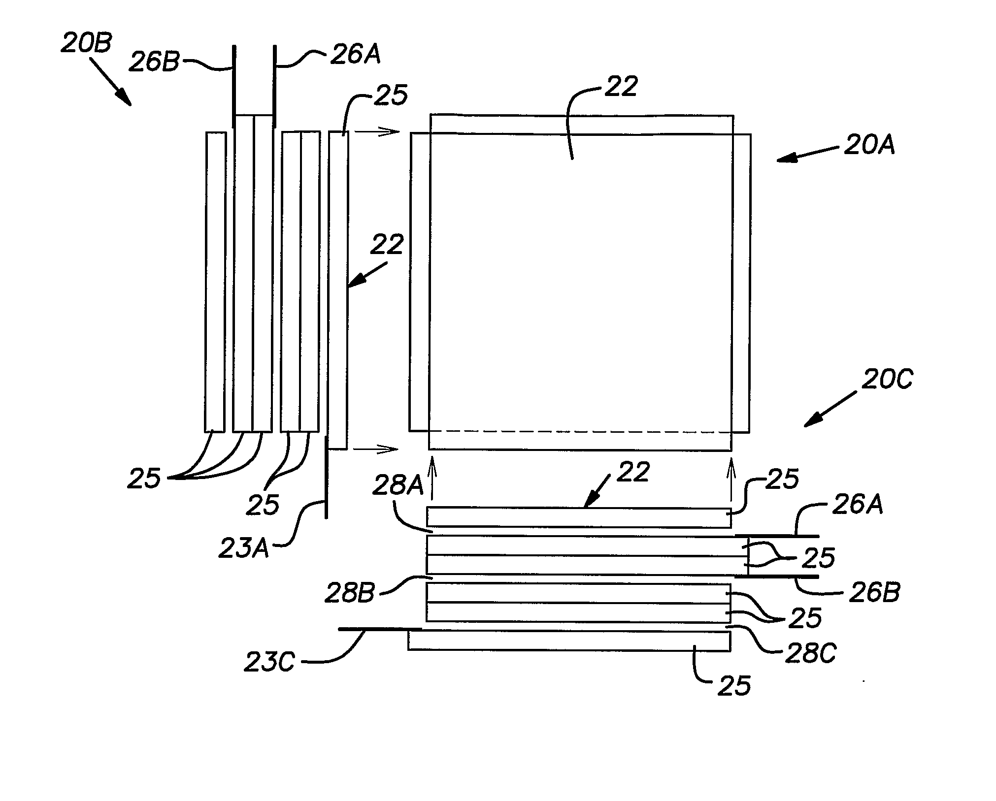
[0042] Reflective display technologies, such as liquid crystal (LC) display materials, and especially those that utilize bistable liquid crystal material, can compensate for some or all of the above-identified problems by developing methods of stacking (or layering) displays of different color characteristics to achieve color pixilation that is not reduced as in the case of spatial distribution of the pixels in one plane. The stacking of bistable LC materials such as ChLCs, for example, is a viable way to produce full color display systems. Reference in this disclosure to “bistable” displays encompasses “multistable” displays that exhibit various stable gray scale levels between the fully reflective or bright (planar) state and the fully nonreflective or dark (focal conic) state.

[0043] Stacking the LC materials such that electromagnetic radiation such as visible light travels successively through a number of layers of the LC material allows a pixel to be designed using a stack of d...


PUM

PropertyMeasurementUnit
drive voltagesaaaaaaaaaa
rotationaaaaaaaaaa
thicknessaaaaaaaaaa

Abstract

A stacked color liquid crystal display uses shared electrode addressing including a plurality of liquid crystal layers each sandwiched between electrically conductive layers. Adjacent liquid crystal layers share one or two electrode layers located between the adjacent liquid crystal layers. A driving scheme is provided that allows the display to be driven by updating the liquid crystal layers sequentially, concurrently, or some combination of the two. Further, a method of manufacturing the display using a deposition process is also disclosed.

Description

RELATED APPLICATIONS [0001] The present application is a 371 of U.S. Patent Application No. PCT / US2005 / 003141, which was published in English on Sep. 9, 2005, which is a continuation of U.S. patent application Ser. No. 11 / 006,100, filed Dec. 7, 2004 (hereinafter “Flexible Display Application”) and Ser. No. 10 / 782,461, filed Feb. 19, 2004, which are incorporated herein by reference in their entireties.[0002] This application was made in part with United States Government support under cooperative agreement DMB07-03-C-J406 awarded by the Defense Advanced Research Projects Agency (DARPA). The government has certain rights in this invention.FIELD OF THE INVENTION [0003] This application relates generally to driving a layered liquid crystal display. [0004] More specifically, this application relates to a color display utilizing layered bistable liquid crystals with shared electrode addressing. BACKGROUND OF THE INVENTION [0005] Bistable displays that do not require continuous voltage app...

Claims


Application Information

Patent Timeline
Patent Type & Authority Applications(United States)
IPC IPC(8): G09G5/00G02F1/13G02F1/1334G02F1/1347G02F1/137
CPCG02F1/1334G02F1/13452G02F1/13473G02F1/13718
Inventor HUANG, XIAO-YANGKHAN, ASAD A.MILLER, NICK M. IV
Owner KENT DISPLAY SYST
Why Eureka
Try Eureka