Method for evaluation of a scattered light signal and scattered light detector used for carrying out said method

a technology of scattered light and detector, which is applied in the field of method for evaluating a scattered light signal and a scattered light detector used for carrying out said method, can solve the problems of increasing the distance between the respective light pulses, increasing the dead area of the detector, and disproportionately shortening the operating life. the effect of reducing the number of detectors

Active Publication Date: 2007-06-21
WAGNER GROUP
View PDF9 Cites 15 Cited by
  • Summary
  • Abstract
  • Description
  • Claims
  • Application Information

AI Technical Summary

Benefits of technology

[0014] Based on the points specified above, the present invention addresses the task of further developing a method for evaluating a scattered light signal to be more effective, more versatile and more exact. The invention furthermore addresses the task of providing a scattered light detector to carry out the above-cited method, its mode of functioning being more precise, more versatile, less prone to errors and less expensive than that of the scattered light detectors known in the art.

Problems solved by technology

Apart from the high energy costs, however, this leads to a disproportionately shortened operating life, especially in the case of laser diodes.
Even if the maximum operational current of an LED is not reached, operation at the maximum upper current limit shortens its lifetime immensely.
The disadvantage to this device, however, is that increasing the distance between the respective light pulses increases the detector's dead area, at the expense of accuracy.
While this device essentially solves the problem of dependency between temperature and light output of the light source, it indicates no possibility of counteracting the change in detector sensitivity, of calibrating the detector, or evaluating the received scattered light signal according to given specifications.

Method used


Image

  • Method for evaluation of a scattered light signal and scattered light detector used for carrying out said method
  • Method for evaluation of a scattered light signal and scattered light detector used for carrying out said method
  • Method for evaluation of a scattered light signal and scattered light detector used for carrying out said method

Examples


first embodiment

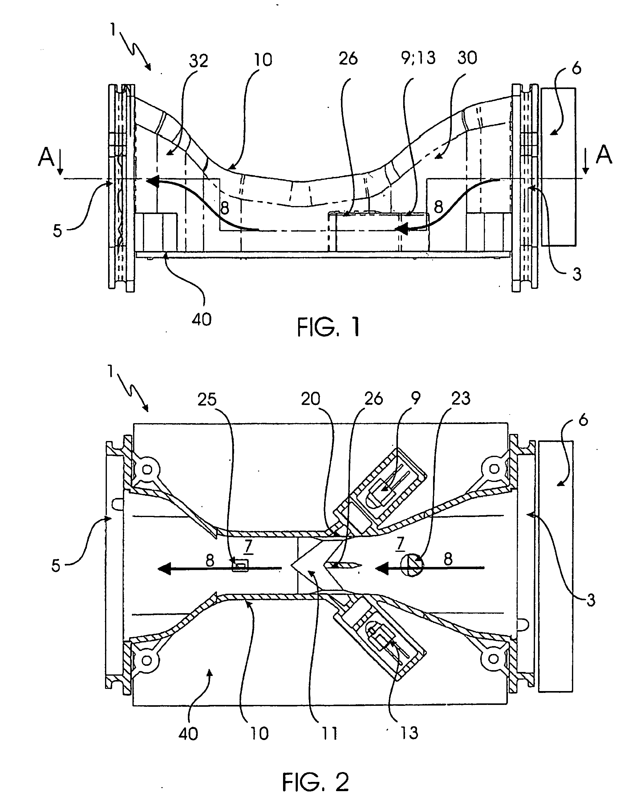
[0044]FIG. 2 shows the first embodiment from FIG. 1 in a sectional top plan view. The orientation to the section corresponds to the A-A intersecting line depicted in FIG. 1. As shown, air, which flows through scattered light detector 1 from inlet opening 3 to outlet opening 5,passes the scattered light center 11. Any fine particles present in air flow 8 thereby reflect the light emitted by light source 9, in this case an LED, onto scattered light receiver 13, which then generates a detection signal once a previously-defined threshold is exceeded. An air flow sensor 25 and a temperature sensor 23 are additionally provided in flow path 7 of the scattered light detector 1. Air flow sensor 25 serves in the assessing of whether a more continuous or some otherwise specific air flow 8 is flowing through scattered light detector 1. In the event of air flow fluctuations, it is, for example, possible to issue a corresponding alarm signal. Temperature sensor 23 monitors the temperature in air ...

second embodiment

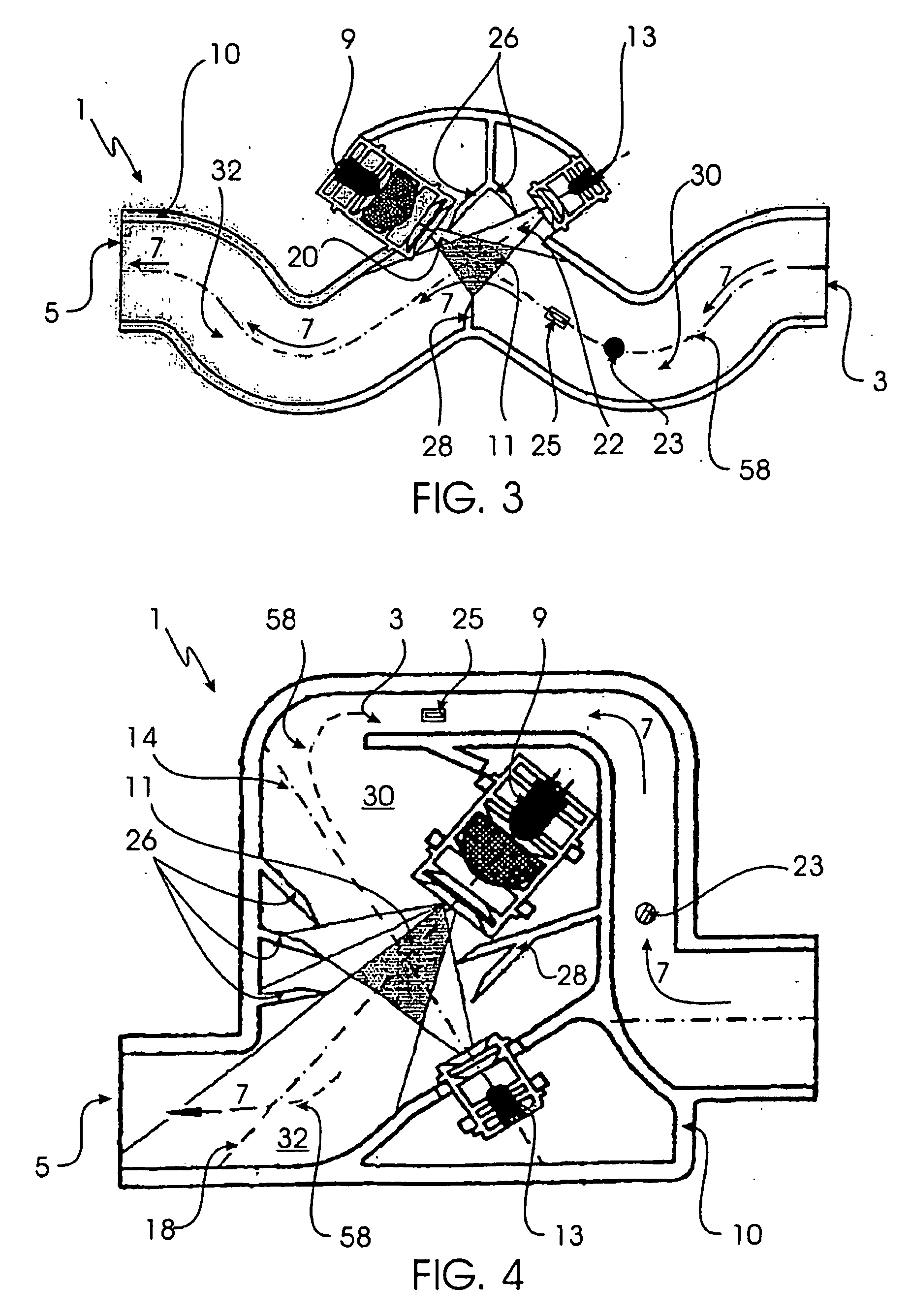
[0046] The second embodiment, shown in FIG. 3, includes screens 26 and 28, which prevent the reflection of the light emitted from the light source 9 directly onto the scattered light receiver 13. A temperature sensor 23 and an air flow sensor 25 are likewise arranged on the center line 58 of flow path 7 to collect the detection-relevant calibration and monitoring data.

third embodiment

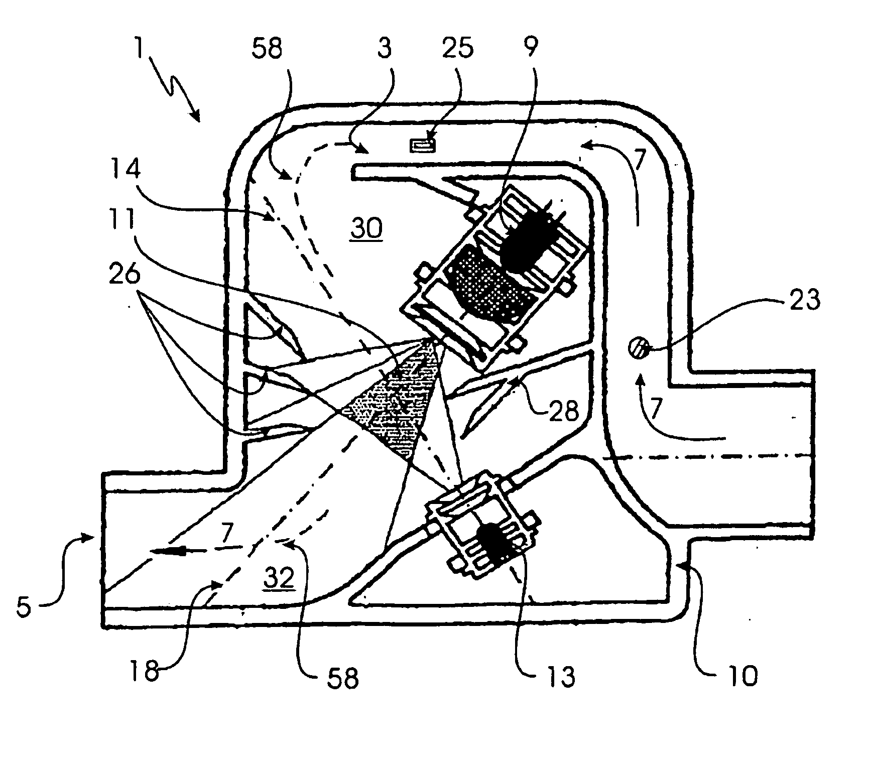
[0047] As in the embodiments depicted before, the third embodiment depicted in FIG. 4 of a scattered light detector also exhibits light traps 30 and 32. The center axes 18 and 14 of the light source 9 and the receiver 13, respectively, are aligned such that they run parallel to or along the center line 58 of flow path 7 for a certain segment thereof (e.g., to the two bendings 30 and 32 of flow path 7). In this embodiment as well, screens 26 and 28 are provided to prevent detection of false values. An air flow sensor 25 and a temperature sensor 23 are likewise arranged in the flow channel formed near inlet opening 3. Thus, the temperature and flow rate of an air flow 8 flowing through scattered light detector 1 is checked before it reaches the scattered light center 11.

[0048] Several processing operations are used in the scattered light detectors 1, as described above. In more detail, the scattered light signal received by scattered light receiver 13 runs through a calibration operat...


PUM

PropertyMeasurementUnit
period of timeaaaaaaaaaa
temperatureaaaaaaaaaa
integration timeaaaaaaaaaa

Abstract

A method of evaluating a scattered light signal generated by a scattered light receiver when detecting especially fine particles in a carrier medium, wherein the scattered light signal runs through a filter algorithm operation to evaluate the scattered light signal subject to specific filter algorithms, the filter algorithm operation being based on a slope of the scattered light signal.

Description

CROSS-REFERENCE TO RELATED APPLICATIONS [0001] This application constitutes the National Stage Entry of the PCT International Patent Application No. PCT / EP2004 / 014632, filed Dec. 22, 2004, and claims the priority of German Patent Application No. 10 2004 004 098.2, filed Jan. 27, 2004, in the German Patent and Trademark Office, the disclosures of which are incorporated herein by reference. [0002] 1. Field of the Invention [0003] An aspect of the present invention relates to a method of evaluating a scattered light signal generated by a scattered light receiver when detecting especially fine particles in a carrier medium. [0004] Another aspect of the present invention relates to a scattered light detector to carry out the above-cited method having a housing, an inlet opening and an outlet opening in said housing, between which the carrier medium flows through the housing on a flow path, having a light source which directs light to a scattered light center lying on the flow path, havin...

Claims


Application Information

Patent Timeline
Patent Type & Authority Applications(United States)
IPC IPC(8): G01N21/00G01N21/53G08B17/107G08B29/04
CPCG01N21/53G08B17/107G08B17/113G01N21/47G08B17/103
Inventor SIEMENS, ANDREAS
Owner WAGNER GROUP
Why Eureka
Try Eureka