
Methods and apparatuses for controlling print density

a technology of density and printing method, applied in the field of printing systems, can solve the problems of page-to-page color shift, insufficient compensation for other halftones, and insufficient approach for other halftones,

Inactive Publication Date: 2007-06-21
XEROX CORP
View PDF2 Cites 36 Cited by
  • Summary
  • Abstract
  • Description
  • Claims
  • Application Information

AI Technical Summary

Benefits of technology

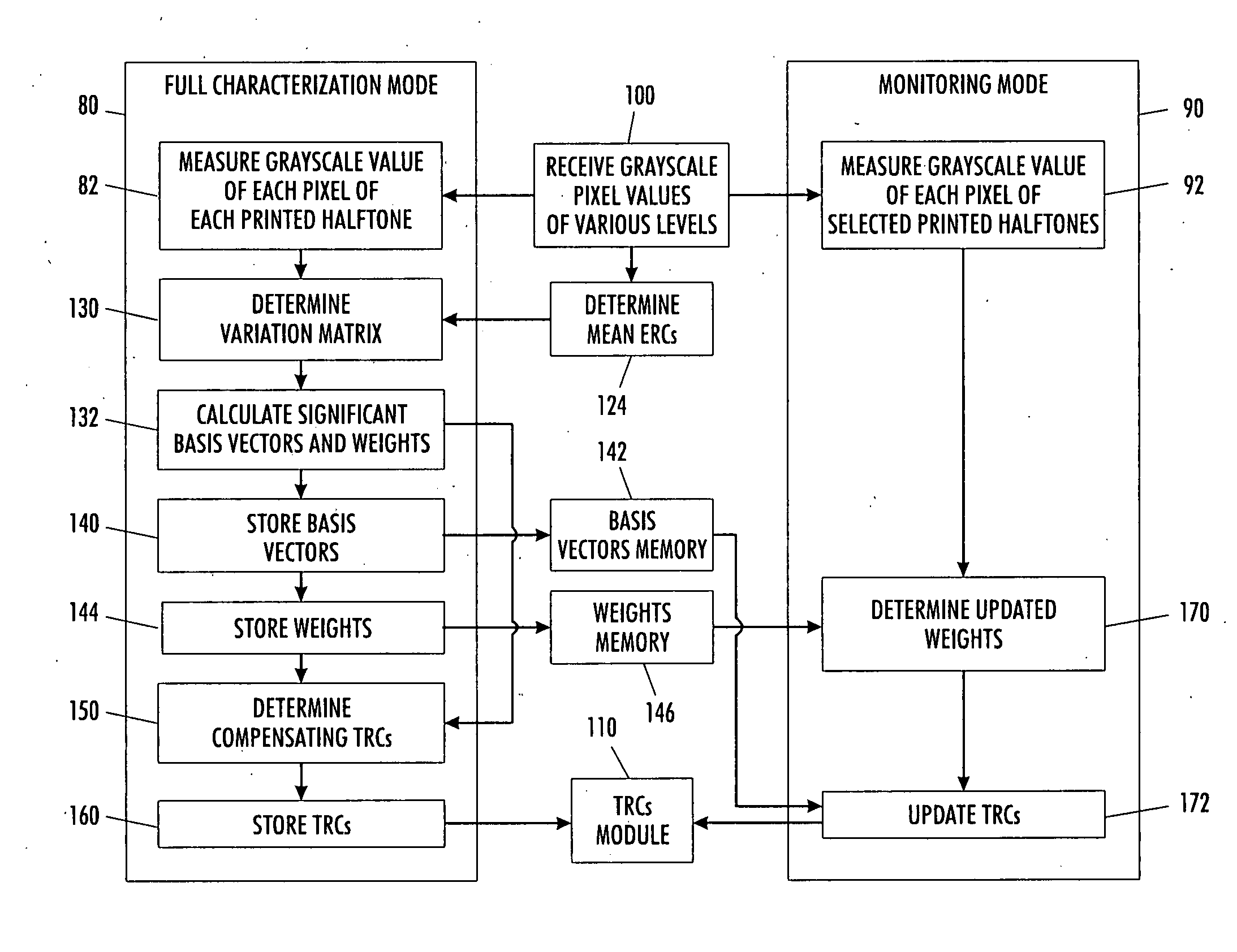
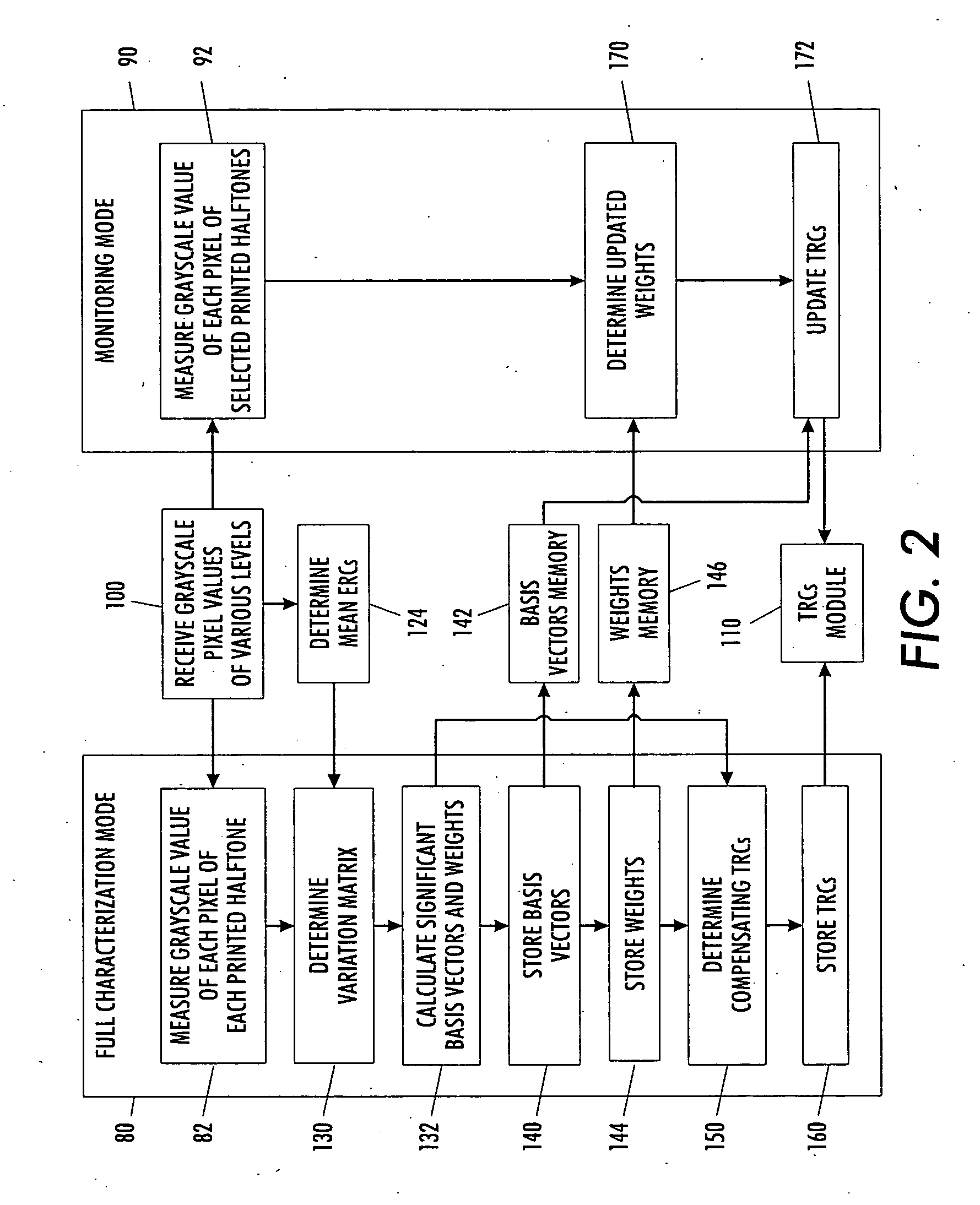
The patent describes a method and system for calibrating a document processing system by measuring the print density of different input grayscale values and determining reference engine response curves. The measured print density values are then transformed into individual components, with one component representing the data content and another component representing the noise content. Based on these components, a set of calibration compensating tone reproduction curves is determined and applied to the input grayscale values to maintain a space of desired uniformity. The technical effect of this patent is to improve the accuracy and consistency of printing documents using a document processing system.

Problems solved by technology

In addition, ERC variation over time may lead to page-to-page color shifts.
If only one halftone is monitored and the compensating TRCs are derived for only the monitored halftone, the compensation may not be adequate for other halftones.
However, since a typical printer prints a plurality of halftones, such approach is costly and time consuming in most applications.
However, these references do not discuss achieving simultaneous uniformity of print density for multiple color separations across the imaging area using reduced tone measurements for different halftone screens.

Method used


Image

  • Methods and apparatuses for controlling print density
  • Methods and apparatuses for controlling print density
  • Methods and apparatuses for controlling print density

Examples


Embodiment Construction

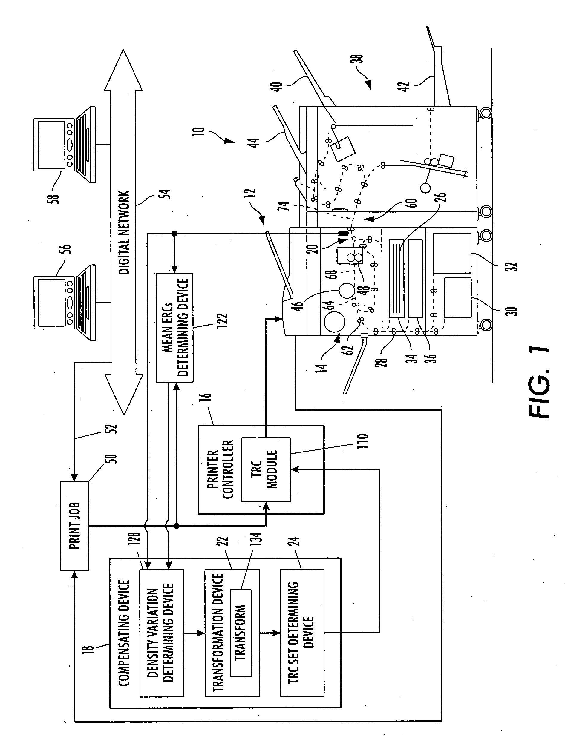
[0033] With reference to FIG. 1, a printing or document processing system 10 includes an image input device 12 such as a scanner, a printer such as a printing or marking engine or printer 14, and a system controller 16, all interconnected by links. The links can be wired or wireless links or other means capable of supplying electronic data to and / or from the connected elements. Exemplary links include telephone lines, computer cables, ISDN lines, and the like. The image input device 12 may include conversion electronics for converting the image-bearing documents to image signals or pixels or such function may be assumed by the marking engine 14.

[0034] As described in greater detail below, a compensating device or algorithm or processor 18 compensates for non uniformity in print density of the printing system over time and space by taking into consideration that the printer outputs a different density for different sub system or component disturbances. A sensor 20 measures print den...


PUM


Abstract

Multiple input patches are received on an output media, which patches are characterized by print density representing a document processing system's response to different input grayscale values over a potential response space. Values associated with the print density of each input grayscale value are measured. Reference Engine Response Curves are determined from the measured print density values and input gray scale values. A variance data representative of a difference between each measured print density value and a respective reference Engine Response Curve is determined. The variance data is transformed into individual components. Based at least on one selected individual component, a set of calibration compensating Tone Reproduction Curves is determined. The determined calibration compensating Tone Reproduction Curves are applied to input grayscale values.

Description

BACKGROUND [0001] The following relates to printing systems. It finds particular application in conjunction with adjusting print uniformity for printing multiple halftones and will be described with the particular reference thereto. However, it is to be appreciated that the following is also amenable to other like applications. [0002] Typically, within the printing system, a digital image gray level value is passed as an input to an image processing module containing functions such as the Tone Reproduction Curve (TRC) for each of the separations. The Tone Reproduction Curve modifies the input gray level value in accordance with the rules determined typically during calibration such as during gray balance as described in Mestha, “Gray Balance Control Loop for Digital Color Printing Systems,” identified below, and provides the modified gray level value to a marking engine. The Engine Response Curve (ERC) of the marking engine describes the printed density as a function of the modified...

Claims


Application Information

Patent Timeline
Patent Type & Authority Applications(United States)
IPC IPC(8): H04N1/46
CPCH04N1/4015H04N1/6033H04N1/6041
Inventor MIZES, HOWARD A.LOCE, ROBERT P.MESTHA, LALIT K.PAUL, PETER
Owner XEROX CORP
Learn More