Fixing apparatus and image forming apparatus using same

a technology of fixing rollers and fixing rollers, which is applied in the direction of electrographic process equipment, instruments, optics, etc., can solve the problems of increasing the adhesive strength of toner, deteriorating image quality of fixed toner image, and surface damage of fixing rollers by separation means

Inactive Publication Date: 2007-06-21
RICOH KK
View PDF4 Cites 30 Cited by
  • Summary
  • Abstract
  • Description
  • Claims
  • Application Information

AI Technical Summary

Benefits of technology

[0013] An object of the present invention is to provide a fixing apparatus that effectively prevents a recording medium from coiling around the surface of a fixing member and does not damage the surface of the fixing member, and an image forming apparatus comprising the fixing apparatus.
[0016] In another aspect of the present invention, an image forming method causes a recording material to carry an image formed by a toner containing at least a resin, a coloring agent, and a wax, and fixing the toner image carried on the recording material onto the recording material using a fixing apparatus. The fixing apparatus comprises a fixing member that is heated by a heat source and a pressure member that is pressed against the fixing member, and fixes an unfixed image on the recording material carrying the unfixed image by passing the recording material between the fixing member and the pressure member. The fixing apparatus further comprises a separating device for separating the recording material from the fixing member following fixing. The separating device comprises a separating member and a spacer attached to the separating member. A gap between the separating member and the fixing member is maintained by bringing the spacer into contact with a structural body of the fixing member.

Problems solved by technology

In this type of heat fixing apparatus, a problem arises in that the unfixed toner carried on the recording medium melts in the nip portion formed by the fixing member and pressure member as the recording medium passes through the nip portion, and the melted toner acts as an adhesive, causing the recording medium to coil around the surface of the fixing member as it is discharged from the nip portion, instead of separating from the surface of the fixing member.
Therefore, a problem arises in that a large amount of toner melts in the nip portion, leading to an increase in the adhesive strength of the toner such that the recording medium coils around the fixing member with particular ease.
However, when the separating means are in constant contact with the fixing roller, the surface of the fixing roller may be damaged by the separating means.
When the surface of the fixing roller is damaged, a new problem arises in that a track mark corresponding to the damage is formed on the toner image that passes through the nip portion, and as a result, the image quality of the fixed toner image deteriorates.
However, the contact member contacts the peripheral surface of the fixing roller, and therefore the surface of the fixing roller may be damaged.
Furthermore, it is not easy to set the interval between the tip end of the separating claw and the fixing member to a correct value, and the correct value may vary according to the machine model, the thickness of the recording medium passing through the nip portion, and the stiffness of the recording medium.
Hence, the only method of determining the correct value of the interval is a process of trial and error for each machine model, and even when the correct value has been set, it may be impossible to prevent coiling effectively due to differences in the material and thickness of the recording material and the effects of static electricity.
With color toner in particular, the part of the toner image that is peeled away from the fixing member by the separating means after coiling around and becoming adsorbed to the fixing member increases in gloss, and therefore gloss unevenness between this part and the other parts of the toner image occurs easily.

Method used


Image

  • Fixing apparatus and image forming apparatus using same
  • Fixing apparatus and image forming apparatus using same
  • Fixing apparatus and image forming apparatus using same

Examples


first embodiment

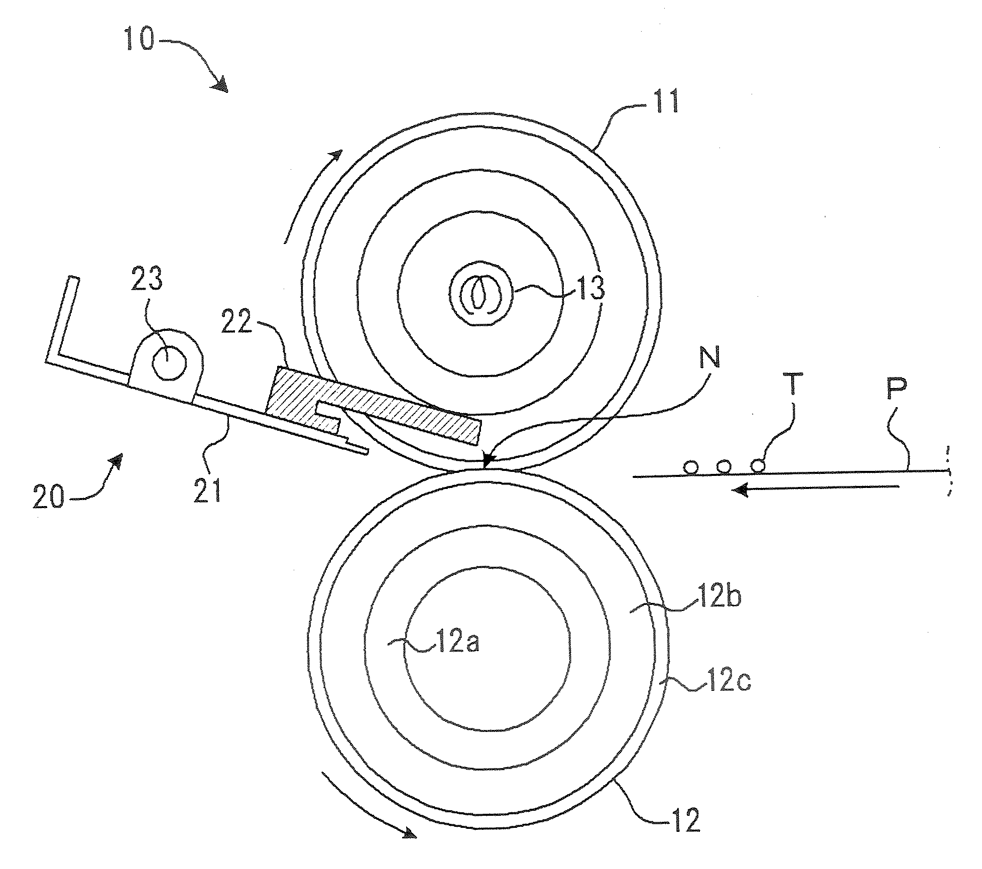
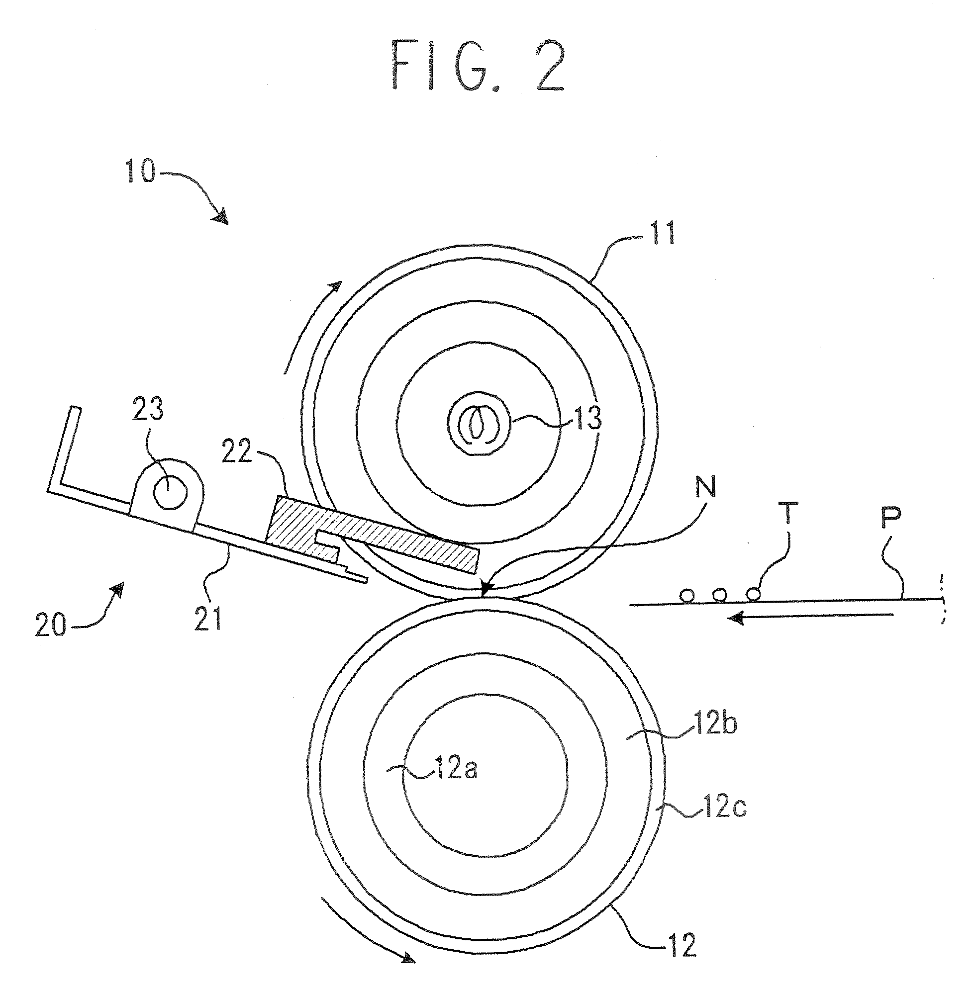
[0029]FIG. 2 shows the structure of the main parts of the fixing apparatus according to the present invention. A fixing apparatus 10 shown in the drawing comprises a fixing roller 11 serving as a fixing member, and a pressure roller 12 serving as a pressure member that is pressed against the fixing roller. The respective peripheral surfaces of the rollers 11, 12 are pressed together to form a nip portion N. The fixing roller 11 and pressure roller 12 are formed in a cylindrical shape having a hollow interior. The fixing roller 11 rotates in the clockwise direction of the drawing, while the pressure roller 12 rotates in the counter-clockwise direction of the drawing. Heating means 13 such as a halogen heater, which are controlled by temperature controlling means not shown in the drawing, are disposed in the interior of the fixing roller 11, and by controlling electrification of the heating means 13, the nip portion N is heated to a suitable temperature for fixing. Transfer paper P se...

second embodiment

[0040]FIG. 4 shows the structure of the main parts of the fixing apparatus.

[0041] A fixing apparatus 30 shown in FIG. 4 comprises a fixing member 40 and a pressure roller 31. The fixing member 40 is constituted by a fixing roller 41, a guide roller 42 serving as a heating roller, and an endless fixing belt 43 wrapped around the fixing roller 41 and guide roller 42. The pressure roller 31 has a built-in heater, and is pressed against the fixing roller 41 via the fixing belt 43. In the fixing apparatus 30 of this embodiment, the pressure roller 31 presses against the fixing belt 43, which is wrapped around the fixing roller 41 and guide roller 42 serving as two guide members, thereby forming the nip portion N.

[0042] The pressure roller 31 is rotated in the counter-clockwise direction of the drawing, while the fixing roller 41 and guide roller 42 are rotated in the clockwise direction of the drawing. As a result, the fixing belt 43 is driven to travel in the clockwise direction of the...

third embodiment

[0048]FIG. 5 shows the structure of the main parts of the fixing apparatus.

[0049] A fixing apparatus 50 shown in FIG. 5 comprises a fixing roller 51 serving as a fixing member, and a pressure member 60. The pressure member 60 is constituted by a pressure roller 61, a guide roller (tension roller) 62, and an endless pressure belt 63 wrapped around the pressure roller 61 and guide roller 62. The pressure roller 61 is pressed against the fixing roller 51 via the pressure belt 63. In the fixing apparatus 50 of this embodiment, the pressure belt 63 wrapped around the pressure roller 61 and guide roller 62, which serve as two guide members, is pressed against the fixing roller 51, thereby forming the nip portion N.

[0050] The fixing roller 51 is rotated in the clockwise direction of the drawing, while the pressure roller 61 and guide roller 62 are rotated in the counter-clockwise direction of the drawing. As a result, the pressure belt 63 is driven to travel in the counter-clockwise direc...


PUM


Abstract

The present invention provides a fixing apparatus which effectively prevents a recording medium from coiling around the surface of a fixing member and also prevents damage to the surface of the fixing member, and an image forming apparatus comprising this fixing apparatus. A gap between the tip end of separating means and the fixing member can be managed appropriately, and as a result, the recording medium can be prevented from coiling around the surface of the fixing member. A spacer is mounted near the tip end of a separating claw, and the spacer contacts a protruding portion of a core metal of a fixing roller. Thus, a gap having a predetermined magnitude is formed between the tip end of the separating claw and the peripheral surface of the fixing roller. The gap is maintained by the spacer, and therefore the gap between the fixing roller and the separating claw can be managed appropriately over the long term. Moreover, paper can be prevented from coiling around the surface of the fixing roller by managing the gap appropriately, and since a contact member contacting the surface (fixing surface) of the fixing roller is not provided, the surface of the fixing roller is not damaged.

Description

BACKGROUND OF THE INVENTION [0001] 1. Field of the Invention [0002] The present invention relates to an image forming apparatus such as a copier, a printer, or a facsimile apparatus, and more particularly to a fixing apparatus capable of preventing a recording medium from coiling around the surface of a fixing member as the recording medium passes through a nip portion formed between the fixing member and a pressure member. [0003] 2. Description of the Background Art [0004] An electrophotographic system image forming apparatus such as a copier performs image formation in which an electrostatic latent image formed on a carrier such as a photosensitive drum is developed by a developing apparatus, whereupon the resulting toner image is transferred onto a recording medium and fixed by a fixing apparatus. Various systems have been proposed in the background art to serve as the fixing apparatus, but a typical, widely used heat fixing apparatus employs a heat roller system in which a press...

Claims


Application Information

Patent Timeline
Patent Type & Authority Applications(United States)
IPC IPC(8): G03G15/20
CPCG03G15/2028
Inventor YAMAMOTO, SHINYAGI, MASAHIRO
Owner RICOH KK
Why Eureka
Try Eureka