
Cleaning blade member

a blade and blade technology, applied in the field of cleaning blade members, can solve the problems of excessive contact pressure with the photoconductor, peeling of the photoconductor, and drooping of the blade edge, and achieve the effect of excellent mechanical characteristics and high durability cleaning

Active Publication Date: 2007-06-21
SYNZTEC
View PDF2 Cites 22 Cited by
  • Summary
  • Abstract
  • Description
  • Claims
  • Application Information

AI Technical Summary

Benefits of technology

[0019] According to the present invention, a high durability cleaning blade member is provided which has excellent mechanical characteristics, such as wear resistance and edge drooping resistance, in any environment.

Problems solved by technology

However, a high degree of hardness of the cleaning blade of a single-layer structure leads to too high a pressure of contact with the photoconductor, posing the problem that a film on the surface of the photoconductor peels off, or the edge of the blade droops.
However, they exhibit satisfactory characteristics in either a high temperature environment or a low temperature environment, and do not show satisfactory characteristics in an environment at high temperatures to low temperatures.

Method used


Image

  • Cleaning blade member
  • Cleaning blade member
  • Cleaning blade member

Examples


example 1

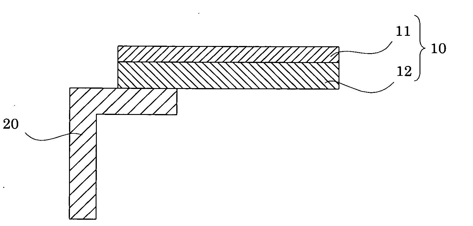
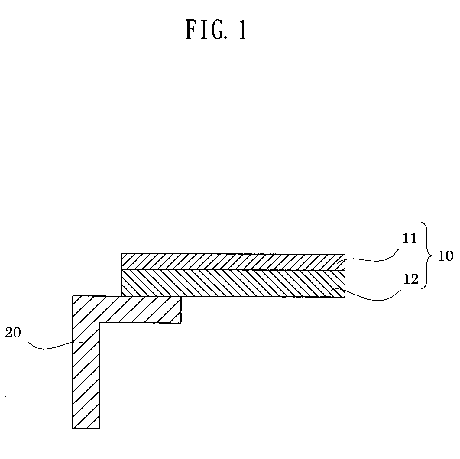
[0066] A back layer and an edge layer were sequentially subjected to centrifugal molding such that the edge layer comprised polyurethane (a) and had a thickness of 0.2 mm and the back layer comprised polyurethane (f) and had a thickness of 1.8 mm, whereby a cleaning blade member was molded. This cleaning blade member was adhered to a metal plate (support member) to form a cleaning blade of Example 1.

example 2

[0067] A cleaning blade of Example 2 was formed in the same manner as in Example 1, except that the edge layer comprised polyurethane (b) and had a thickness of 0.5 mm and the back layer had a thickness of 0.5 mm.


PUM


Abstract

A cleaning blade member for use in a cleaning section for removing toner on a toner-deposited body, the cleaning blade member comprising: an edge layer contacting the toner-deposited body; and a back layer provided on a back side of the edge layer, and wherein the edge layer has a Young's modulus of 8 to 20 MPa and an impact resilience at 25° C. of 20 to 40%, and when the Young's modulus of the edge layer is designated as Ea, a Young's modulus of the back layer is designated as Eb, a thickness of the edge layer is designated as Ta, and a thickness of the back layer is designated as Tb, a ratio (Rb / Ra) between a contribution rate Ra of the Young's modulus of the edge layer represented by the following equation (1), and a contribution rate Rb of the Young's modulus of the back layer represented by the following equation (2) is 0.01 to 6.0, and a total Young's modulus (Ra+Rb) of the edge layer and the back layer is 7 to 14 MPa: Ra=[TaEa / (Ta+Tb)]  (1) Rb=[TbEb / (Ta+Tb)]  (2)

Description

[0001] The entire disclosure of Japanese Patent Applications Nos. 2005-365559 filed Dec. 19, 2005 and2006-331111 filed Dec. 7, 2006 is expressly incorporated by reference herein. BACKGROUND OF THE INVENTION [0002] 1. Field of the Invention [0003] This invention relates to a cleaning blade member, and more particularly, to a cleaning blade member for removing a toner on a toner image bearing body, on which a toner image is formed and from which the toner image is transferred onto a material for receiving the toner image, such as a photoconductor or a transfer belt in electrophotography. [0004] 2. Description of the Related Art [0005] With the electrophotographic process, a cleaning blade for removing a toner is generally used to use an electrophotographic photoconductor or a transfer belt repeatedly. Since the cleaning blade makes contact with the photoconductor for a long term, it is required to have satisfactory wear resistance and a low coefficient of friction. In recent years, as...

Claims


Application Information

Patent Timeline
Patent Type & Authority Applications(United States)
IPC IPC(8): G03G21/00
CPCG03G2221/0005G03G21/0017
Inventor UENO, MIYUKIABE, SHUJI
Owner SYNZTEC
Features
  • Generate Ideas
  • Intellectual Property
  • Life Sciences
  • Materials
  • Tech Scout
  • Unparalleled Data Quality
  • Higher Quality Content
  • 60% Fewer Hallucinations
Learn More