Refractive intraocular implant lens and method
a technology of intraocular implants and lenses, applied in the field of intraocular implant lenses, can solve the problems of difficult lens implanting, hard material, non-flexible material, etc., and achieve the effect of easy insertion and removal with minimal trauma to eye tissues
- Summary
- Abstract
- Description
- Claims
- Application Information
AI Technical Summary
Benefits of technology
Problems solved by technology
Method used
Image

Examples
first embodiment
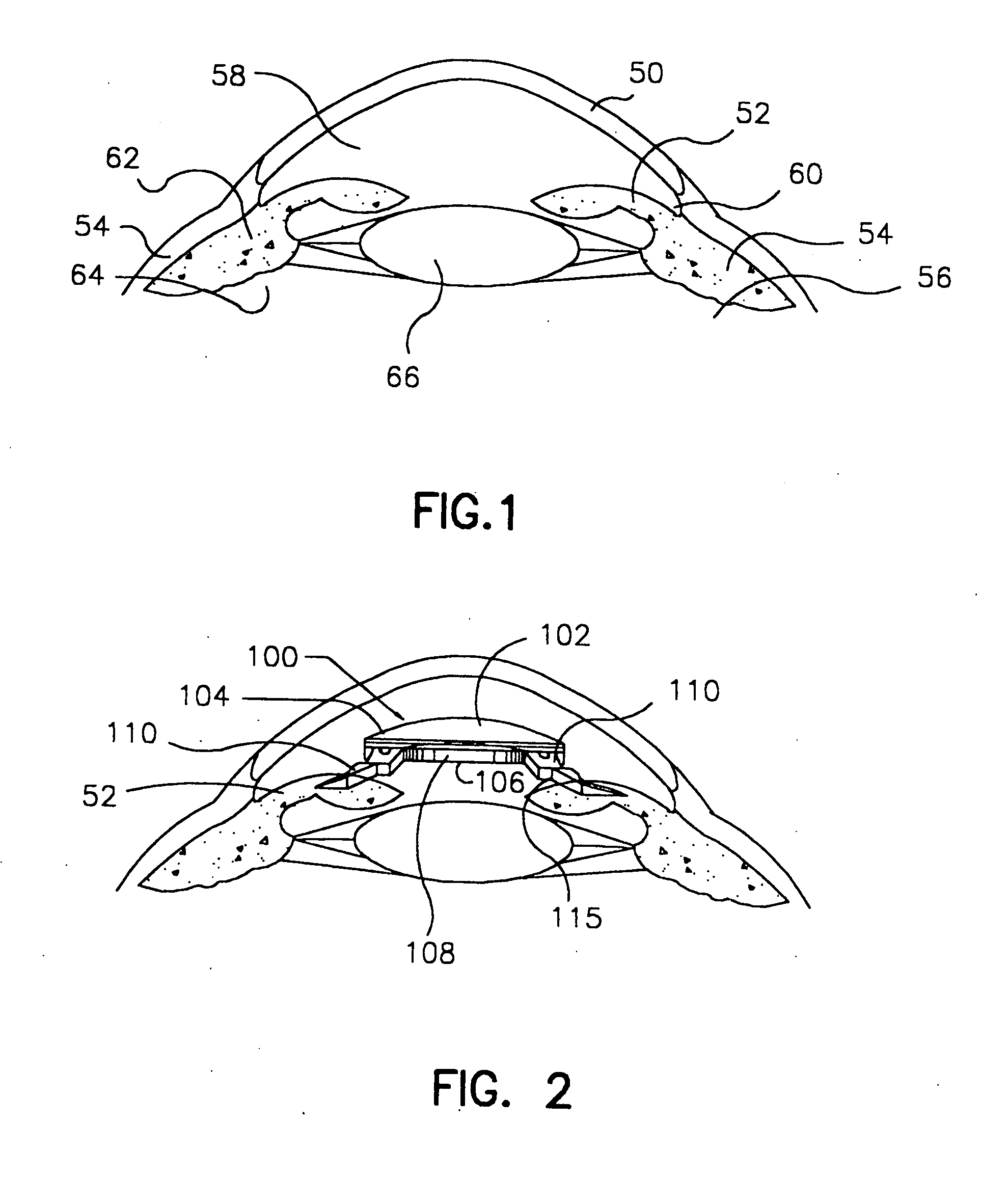
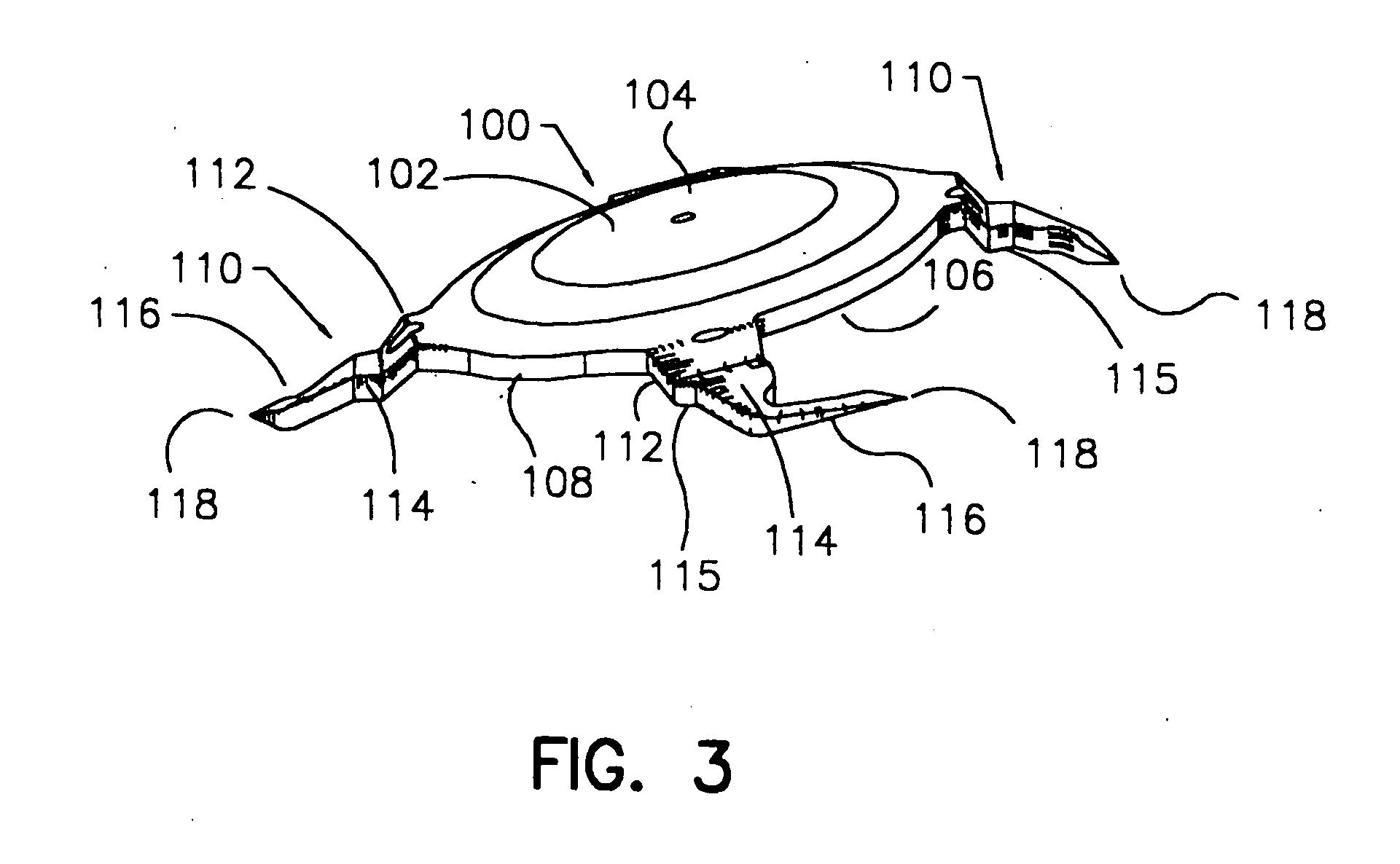
[0046] Turning now to FIGS. 2 through 8, the invention is there illustrated. The intraocular lens generally indicated at 100 is adapted to be implanted within the eye and includes an optical means or optic 102 and a single or a plurality of haptic means or haptics 110. The optic is generally circular and has an anterior side 104, a posterior side 106 and an outer peripheral edge 108. The diameter of the optic 102 is in the range of approximately 5 mm to 6 mm. In addition, the optic 102 will have varying anterior and posterior curvatures, depending on whether myopia or hyperopia is being corrected. Further curvature variations are added for the correction of cylinder (Astigmatism), presbyopia, bi-focal or multi-focal. The characteristics of the particular optic 102 selected are left to the surgical judgment of the ophthalmologist performing the implant procedure. In addition, the optic 102 and the haptics 110 must be made of a material, which is biologically inert and the optic 102 m...
second embodiment
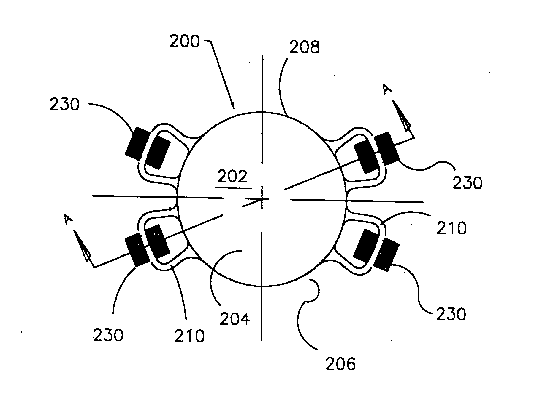
[0049] the invention is illustrated in FIGS. 9 through 14 wherein an optical implant 200 is adapted to be implanted within the eye and to be attached to the iris. The implant comprises an optical means or optic 202 for producing a preselected optical effect. The optic 202 has an anterior side 204, a posterior side 206 and an outer peripheral edge 208. A single or plurality of haptic means or haptics 210 are connected to the optic 202. A staple means or staple 230 is adapted to straddle a portion of said haptic 210. The staple 230 is adapted to be manipulated from a relaxed state to a tensioned state whereupon it is released and attaches to the iris. In the illustrated embodiment, the staple in the relaxed state is expanded. It is then compressed (with an insertion tool discussed hereinbelow), placed in overlying straddling relation to the respective haptic(s), and upon release, expands to substantially return to its original state, thereby fixing the position of the optical implant ...
third embodiment
[0052] the invention is illustrated in FIGS. 15 through 17. In that embodiment an optical means or implant 300 for producing a preselected optical effect on light entering the eye and adapted to be implanted in overlying relation to the iris 52 is employed. The implant 300 includes an anterior side 302 and a posterior side 304 and an outer peripheral edge 306. A single or plurality of haptic means or haptics 308 are connected to the implant 300 such that at least one includes a hole defining an opening 310. A fastening means 312 for fixing the position of the intraocular lens on the iris is provided.
[0053] The fastening means or fastener 312 is adapted to be inserted within the opening 310 and to expandingly grip the iris tissue. More specifically, the fastening means 312 comprises a shaft having a top end 314 and a bottom end 316. Located at the bottom end 316 is a flexible barb 318 and the top end 314 has a diameter that is greater than the diameter of opening 310. As illustrated ...
PUM
 Abstract
Description
Claims
Application Information
 - R&D Engineer
- R&D Manager
- IP Professional
- Industry Leading Data Capabilities
- Powerful AI technology
- Patent DNA Extraction
Browse by: Latest US Patents, China's latest patents, Technical Efficacy Thesaurus, Application Domain, Technology Topic.
© 2024 PatSnap. All rights reserved.Legal|Privacy policy|Modern Slavery Act Transparency Statement|Sitemap