Eureka AIR delivers breakthrough ideas for toughest innovation challenges, trusted by R&D personnel around the world.

Cap for button, fixing member and button

Inactive Publication Date: 2007-06-28
YKK CORP
View PDF11 Cites 3 Cited by
  • Summary
  • Abstract
  • Description
  • Claims
  • Application Information

AI Technical Summary

Benefits of technology

[0015]An object of the present invention is to solve the aforesaid problems and to provide a cap for a button, a fixing member and a button which provide improved material use efficiency, reduced load in clinching, alteration prevention due to remaining liquid, rotation prevention of the cap and the like.

Problems solved by technology

(a) In a blanking process of the circular plate blanks 36 out of the plate material, when the circular plate blanks 36 with the outer circumferences contacting to each other, the outer circumferences may be deformed, so that the blanked-out circular plate blanks 36 are not accurate. To prevent this problem, the adjacent circular plate blanks 36 are disposed with a margin of about 1 mm therebetween in the blanking process of the circular plate blanks 36. After the blanking process, the margin portion is left in a frame shape in the plate material. Thus, the deformation of the outer circumference of the blank 36 is avoided of the blanked in a contacting state with no bridge, such circular plate blanks 36 cannot be accurate. However, providing the margin may reduce the material use efficiency.
(b) When clinching the short cylindrical cap 31 obtained by drawing the circular plate blank 36 to a component of the button (for example, the fixing member main body 21), the end of the holding portion 34 continuously extending from the outer periphery of the main surface covering portion 32 needs to be curled inward. In other words, the entire circumference of the peripheral wall of the cylindrical holding portion 34 needs to be clinched, requiring a large load. Hence, a punch or a die used for clinching may be damaged.
(c) When a garment with the above-described button is soaked in a liquid for washing or decoration, the liquid may remain in the cap 31 especially in an inner space of the curled portion of the cylindrical holding portion 34, which may cause discoloration or degradation of the garment.
(d) In a state in which the cap 31 is clinched to the fixing member main body 21, the entire circumference of the cylindrical holding portion 34, that is, the entire circumference of the clinched portion is curled inward to abut to the fixing member main body 21. Accordingly, when the fixing member main body 21 or the cap 31 has a circular shape, the cap 31 may easily rotate relative to the fixing member main body 21. Hence, when the cap 31 has an image pattern or a character thereon, the orientation of the image pattern or the character may vary. It is not preferable in terms of design.

Method used


Image

  • Cap for button, fixing member and button
  • Cap for button, fixing member and button
  • Cap for button, fixing member and button

Examples


Embodiment Construction

)

[0046]An embodiment of the invention will be described below with reference to the attached drawings.

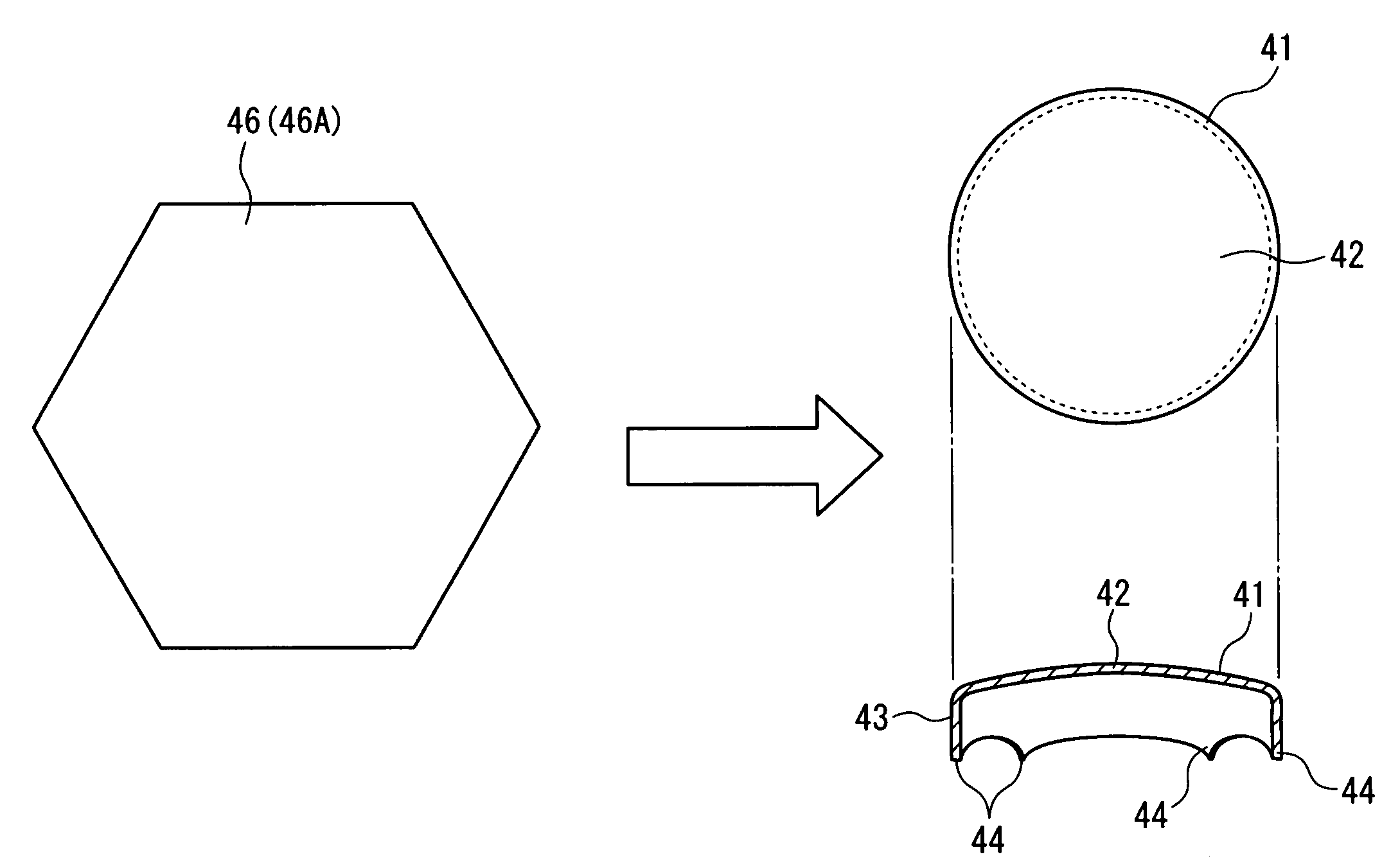
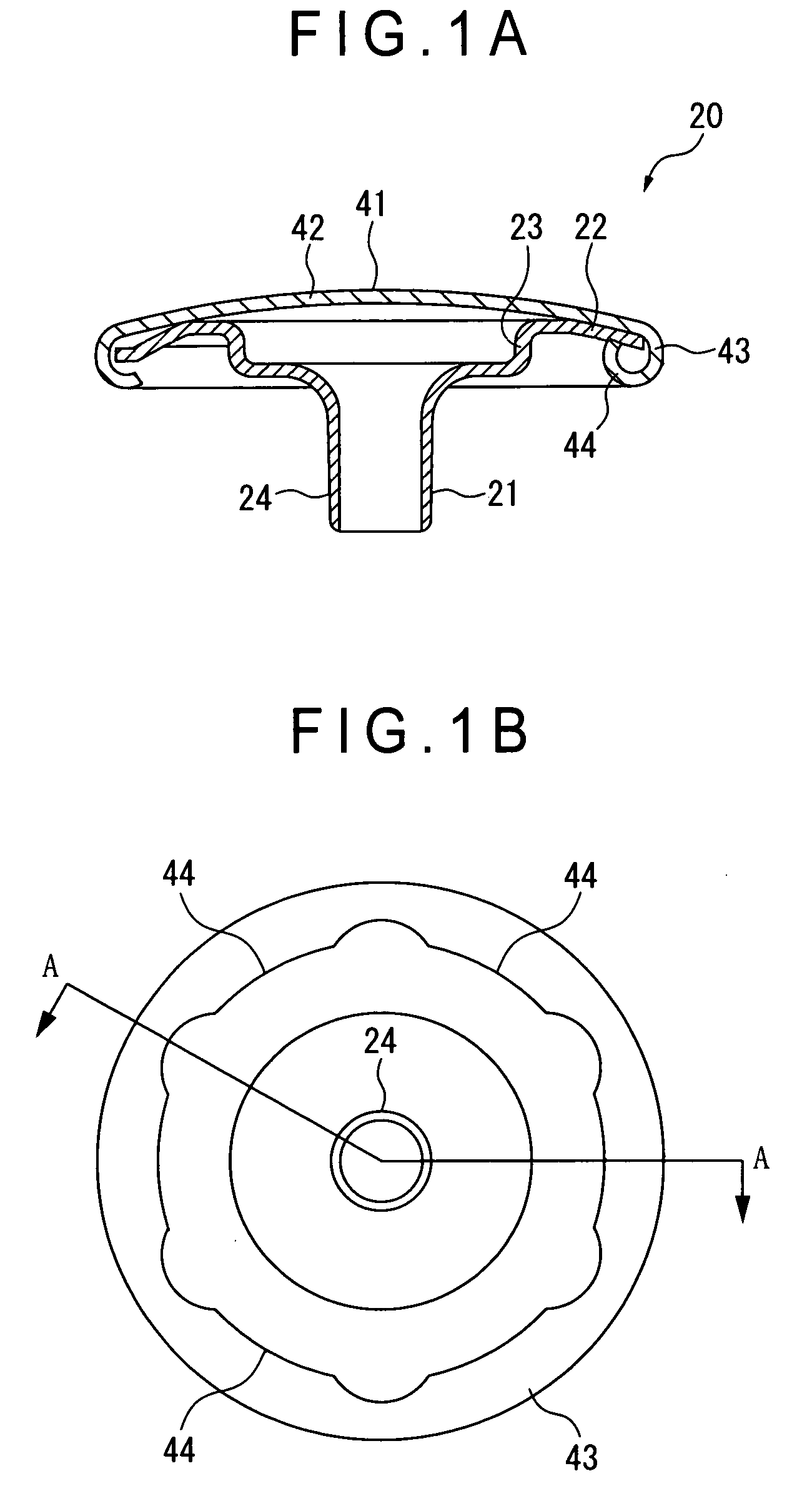
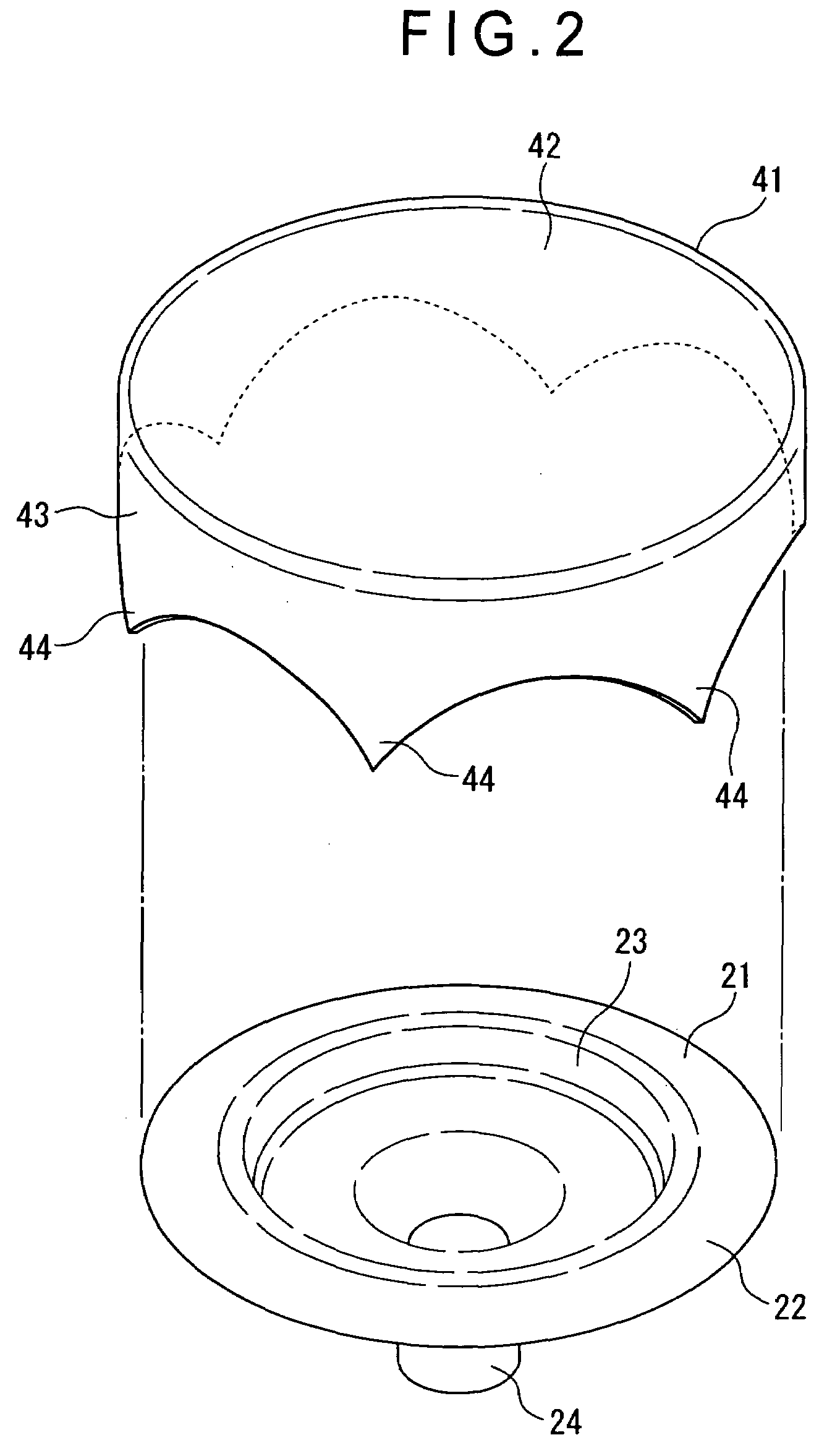
[0047]The embodiment is an application example to a fixing member 20 of a female button described above. FIGS. 1A and 1B are respectively a cross sectional view and a bottom view of a fixing member 20 according to the embodiment. FIG. 1A is a cross section taken along the A-A line of FIG. 1B. FIG. 2 is an exploded perspective view of FIGS. 1A and 1B.

[0048]As shown in FIGS. 1 and 2, the fixing member 20 of the embodiment penetrates a fabric 1 from one surface to the other surface. The fixing member 20 includes a fixing member main body 21 for holding a button main body on the other surface of the fabric 1 (see a button main body 10 in FIG. 9) and a cap 41 for covering an outer surface of the fixing member main body 21 on the other surface side. The fixing member main body 21 is the same as the fixing member main body 21 of FIG. 9. Only the difference is that the cap 41 is not the sam...


PUM


Abstract

Provided is a cap (41) for a button, of which material is a polygonal plate. The cap (41) includes a main surface covering portion (42) formed substantially at the center of the polygonal plate and a plurality of holding piece portions (44) formed by bending corners of the polygonal plate from an outer peripheral end of the main surface covering portion (42) to a rear surface side of the main surface covering portion (42). Provided between the main surface covering portion (42) and the plurality of holding piece portions (44) is a lateral side covering portion (43) around the outer peripheral end of the main surface covering portion (42).

Description

BACKGROUND OF THE INVENTION[0001]1. Field of the Invention[0002]The present invention relates to a button cap for covering an outer surface of a button, a fixing member for fixing a button main body to a fabric and a button using the button cap or the fixing member, which are for buttons for holding mating portions of a garment or ornamental buttons mainly used for decorative purposes.[0003]2. Description of Related Art[0004]Buttons include buttons for holding mating portions of a garment and ornamental buttons mainly used for decorative purposes. Such buttons each include a male button and a female button which are fitted to each other. Generally, the male button is attached on one of the mating portions of a fabric and the female button is attached on the other mating portion such that the male and female buttons face each other. By fitting the male button in the female button, the mating portions of the fabric are held together.[0005]The male and female buttons each have a button...

Claims


Application Information

Patent Timeline
IPC IPC(8): A44B1/00
CPCA44B1/08A44B17/0082Y10T24/367Y10T24/3672Y10T24/3698
Inventor TAKAMURA, YOSHIO
Owner YKK CORP
Why Eureka
Eureka Blog
Learn More