Apparatus for detecting rotational angle

Inactive Publication Date: 2007-06-28
HON HAI PRECISION IND CO LTD
View PDF4 Cites 0 Cited by
  • Summary
  • Abstract
  • Description
  • Claims
  • Application Information

AI Technical Summary

Problems solved by technology

The decoding translator generally includes complex circuitry, thus, the decoding translator increases the complexity of the apparatus for detecting rotational ang

Method used


Image

  • Apparatus for detecting rotational angle
  • Apparatus for detecting rotational angle
  • Apparatus for detecting rotational angle

Examples


Embodiment Construction

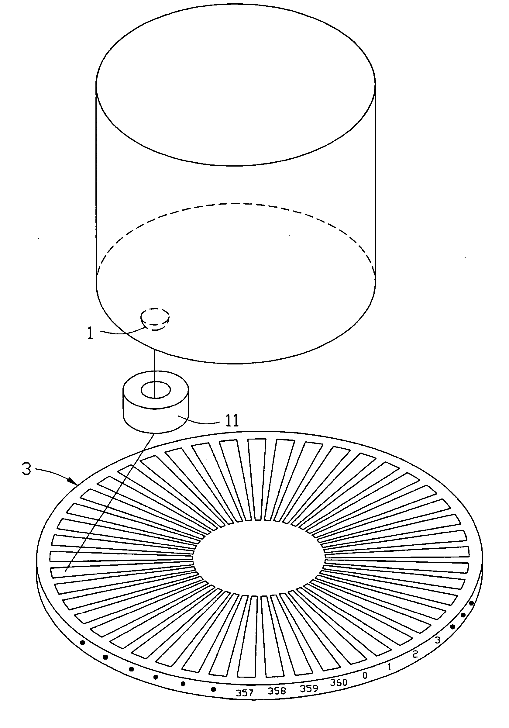
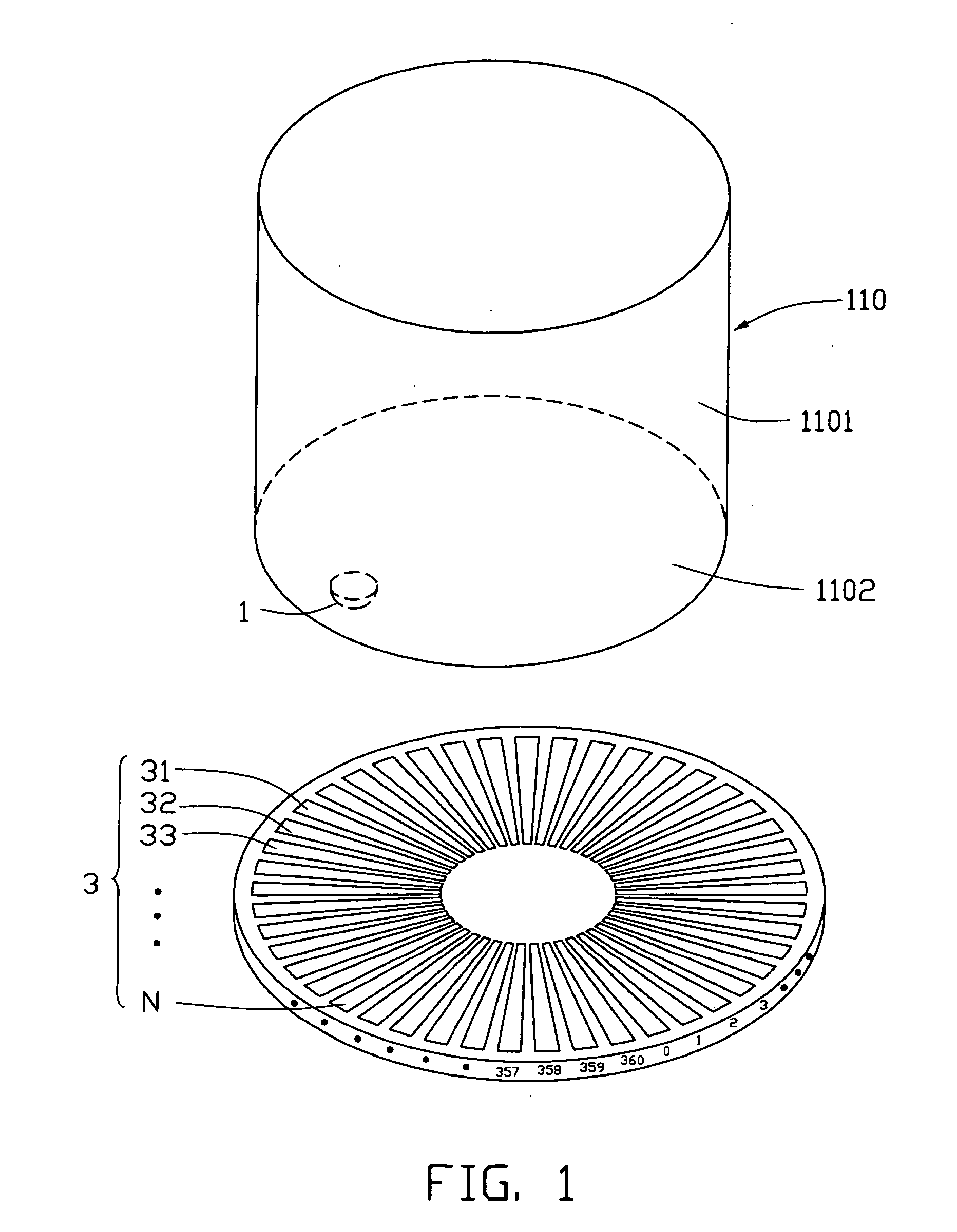
[0013] Referring to FIG. 1, in a first embodiment, the apparatus 100 for detecting a rotational angle of a rotational element 110 such as a cylindrical product includes a light emitting element 1 and an image detecting element 3. The rotational element 110 includes a circumferential surface 1101 and an end surface 1102.

[0014] The light emitting element 1 is disposed at the end surface 1102 of the rotational element 110 so as to rotate together with the rotational element 110 and emits light in a direction substantially parallel to a rotational axis of the rotational element 110. The light emitting element 1 can also be disposed at the circumferential surface 1101 of the rotational element 110.

[0015] The image detecting element 3 is disposed at a position so as to receive the light emitted by the light emitting element 1, for example, at a mounting stage facing the end surface 1102 and perpendicular to the rotational axis of the rotational element 110. The image detecting element 3...


PUM


Abstract

An apparatus (100) for detecting rotational angle of a rotational element (110), includes a light emitting element (1) and an image detecting element (3). The light emitting element is disposed on the rotational element to emit light. The image detecting element has a plurality of reception zones (31, 32 . . . N) for receiving the light emitted. Each of the reception zones corresponds to an angular section of the rotational element.

Description

BACKGROUND OF THE INVENTION [0001] 1. Field of the Invention [0002] The present invention generally relates to a detecting apparatus and, more particularly, to an apparatus for detecting rotational angle or position. [0003] 2. Discussion of the Related Art [0004] In the process of manufacturing cylindrical products, apparatuses for detecting rotational angle are generally used to detect the rotational angle or position of the cylindrical products so that cylindrical products can be effectively manufactured to a required shape. One such apparatus for detecting rotational angle typically includes a signal emitter disposed on the cylindrical product, a signal receiver disposed on a stage facing the signal emitter and perpendicular to an axis of the cylindrical product, and a display. To detect the rotational angle of the cylindrical product, the signal emitter transmits an electrical signal from the cylindrical product to the signal receiver, this signal is then converted into a visibl...

Claims


Application Information

Patent Timeline
IPC IPC(8): G01D5/34
CPCG01D5/3473
Inventor CHIU, WEN-SSU
Owner HON HAI PRECISION IND CO LTD
Why Eureka
Try Eureka