System and method for creating minimum bounding rectangles for use in a geo-coding system

a geo-coding system and minimum bounding rectangle technology, applied in the field of geo-coding, can solve the problems of not showing relevant advertisements, user may be presented with irrelevant or useless advertisements, and useful advertisements may not be displayed

Active Publication Date: 2007-06-28
R2 SOLUTIONS
View PDF21 Cites 41 Cited by
  • Summary
  • Abstract
  • Description
  • Claims
  • Application Information

AI Technical Summary

Problems solved by technology

Often, however, relevant advertisements are not displayed even though the advertiser's business is relevant and located near the location queried by the user.
Further, advertisements may be displayed even though the business is irrelevant or the advertiser does not actually serve the location queried by the user.
Accordingly, a user may be presented with irrelevant or useless advertisements while relevant and useful advertisements fail to be displayed.
However, the results of FIG. 7 demonstrate that the traditional geo-coding processors are unable to differentiate the context (restaurants) from the geography (Pacific Heights).
Clearly these results are not helpful to the user searching for restaurants in Pacific Heights.
However, there are several drawbacks to using the circle / radius calculations.
It is too resource intensive to analyze every point along both circles to determine if the circles overlap.
Thus, even if the dentist in Altadena serves patients in Pasadena, the user in Pasadena may be unable to see the dentist's advertisement.
Other drawbacks of using the traditional circle / radius method include the inadequate representation of the often jagged, uneven boundaries of geographic features.
It may be difficult if not impossible to use circles to represent these geographical features.
Another drawback may be that advertisers will often purchase large circles in order to target large areas.
Thus the advertiser pays for clicks or calls from users that the advertisers cannot serve.
If the minimum bounding rectangles were not constructed over the polygons representing the respective regions then this calculation would be almost impossible.
To calculate the vast number of line segments that make up these polygons is extremely resource intensive.
As such, an address of Sunnyvale, Silicon Valley, Calif. would work in the geo-coding system 100, whereas it would cause difficulties for the simple lookup tables traditionally used in geo-coding systems.
Additionally, the illustrations are merely representational and may not be drawn to scale.

Method used


Image

  • System and method for creating minimum bounding rectangles for use in a geo-coding system
  • System and method for creating minimum bounding rectangles for use in a geo-coding system
  • System and method for creating minimum bounding rectangles for use in a geo-coding system

Examples


Embodiment Construction

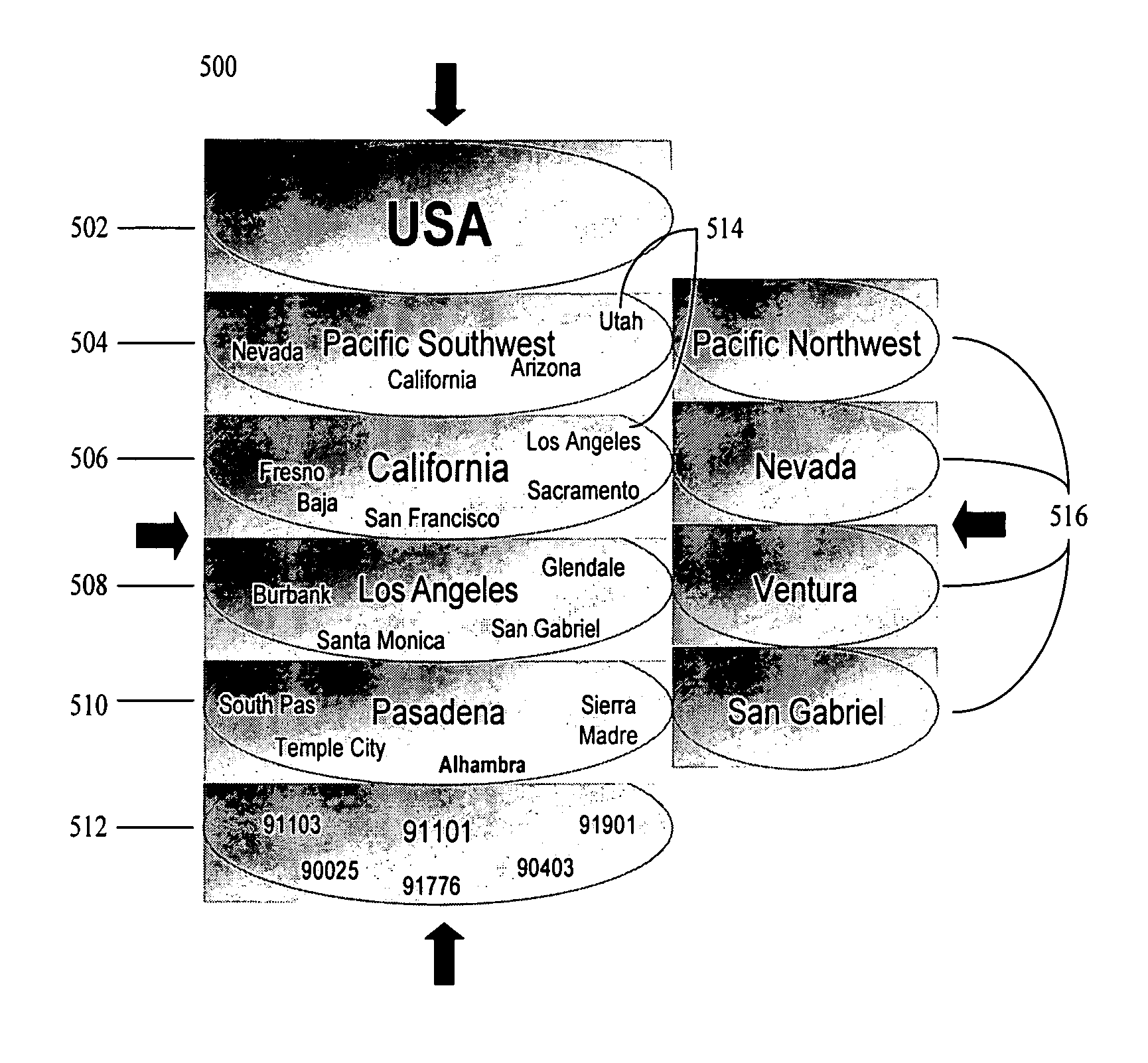
[0018] The disclosed embodiments relate generally to geo-coding, and more particularly, but not exclusively, to geo-coding based on spatial geometry. The principles described herein may be embodied in many different forms. The systems and methods may allow search engines, advertisers or other e-commerce entities to provide users with geographically relevant information based on the user's search query or other information directly or indirectly provided by the user which has geographic relevance. The disclosed systems and methods may allow search engines to match users with geographically relevant advertising and media. The systems and methods may allow businesses to target users with geographically relevant advertisements and media. Further, the disclosed systems and methods minimize the amount of processing necessary to analyze geographic relevance and determine geographic relationships by minimizing the number of potential hierarchical and adjacent relationships of a given geogra...


PUM


Abstract

A method is disclosed for determining a minimum bounding polygon for use in a geo-coding system. A first polygon is received defining a geographic region. A minimal number of points is determined corresponding to the first polygon to define a second polygon at least bounding the first polygon.

Description

TECHNICAL FIELD [0001] The present embodiments relate generally to geo-coding, and more particularly, but not exclusively, to geo-coding based on spatial geometry. BACKGROUND [0002] Geo-coding enables enterprises to apply geographic coordinates to named entities, such as place names, street addresses or other entities associated with a specific physical location. Geo-coding may provide an important source of revenue for e-commerce enterprises, such as Internet based search engines, advertisers, etc. E-commerce enterprises provide results to a user based on the user's entered query terms or other relevant information. In this regard, such enterprises may provide advertising and other information or content to the user. [0003] For example, a user may conduct an on-line search for a coffee shop in San Francisco. In response thereto, advertisements may be displayed to the user for advertisers having coffee shops or other related businesses located near the location queried by the user. ...

Claims


Application Information

Patent Timeline
Patent Type & Authority Applications(United States)
IPC IPC(8): G06F17/00
CPCG06F17/30241G06F17/3087G06F16/9537G06F16/29
Inventor RIISE, SORRENPATEL, DEV
Owner R2 SOLUTIONS
Why Eureka
Try Eureka