Timepiece with a constant-force device for acting on an oscillating system

a constant force device and oscillating system technology, applied in the field of timepieces, can solve the problems of high torque on the camera plate, and achieve the effects of low frictional force, low installation space, and low level of for

Active Publication Date: 2007-06-28
LANGE UHREN
View PDF8 Cites 33 Cited by
  • Summary
  • Abstract
  • Description
  • Claims
  • Application Information

AI Technical Summary

Benefits of technology

[0013] A largely direct transfer of force from the spring barrel to the secondary spring-energy store is achieved in a manner which is straightforward and reduces the amount of installation space required if an intermediate tube which is coaxial with the seconds shaft is driven in a rotatable manner by way of the spring barrel, in particular via a third wheel. The intermediate tube has a drive wheel, for driving the stop wheel in a rotatable manner, and a retaining plate, which is connected to the secondary spring-energy store.

Problems solved by technology

This design results in a largely direct transfer of force from the primary spring-energy sto

Method used


Image

  • Timepiece with a constant-force device for acting on an oscillating system
  • Timepiece with a constant-force device for acting on an oscillating system
  • Timepiece with a constant-force device for acting on an oscillating system

Examples


Embodiment Construction

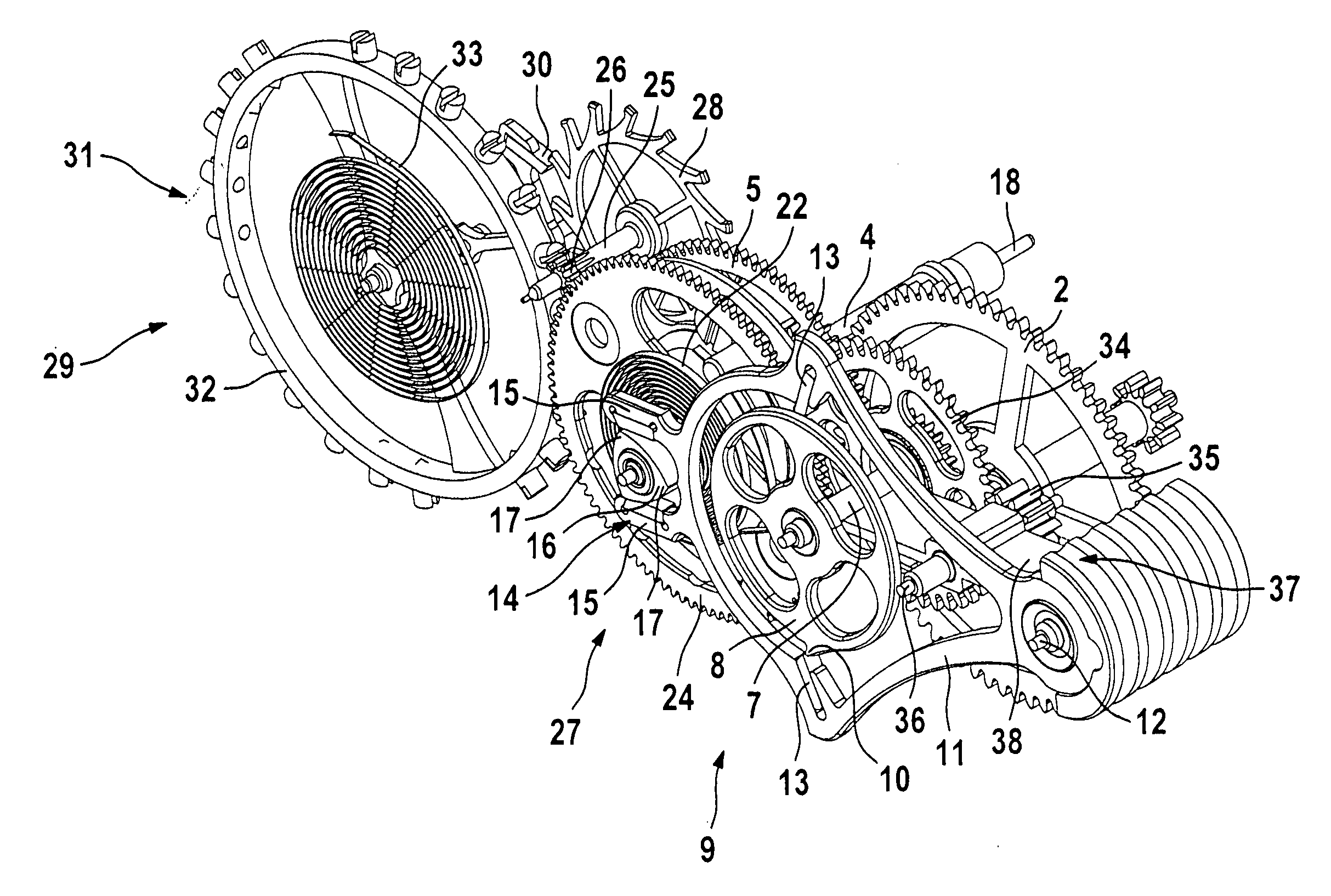
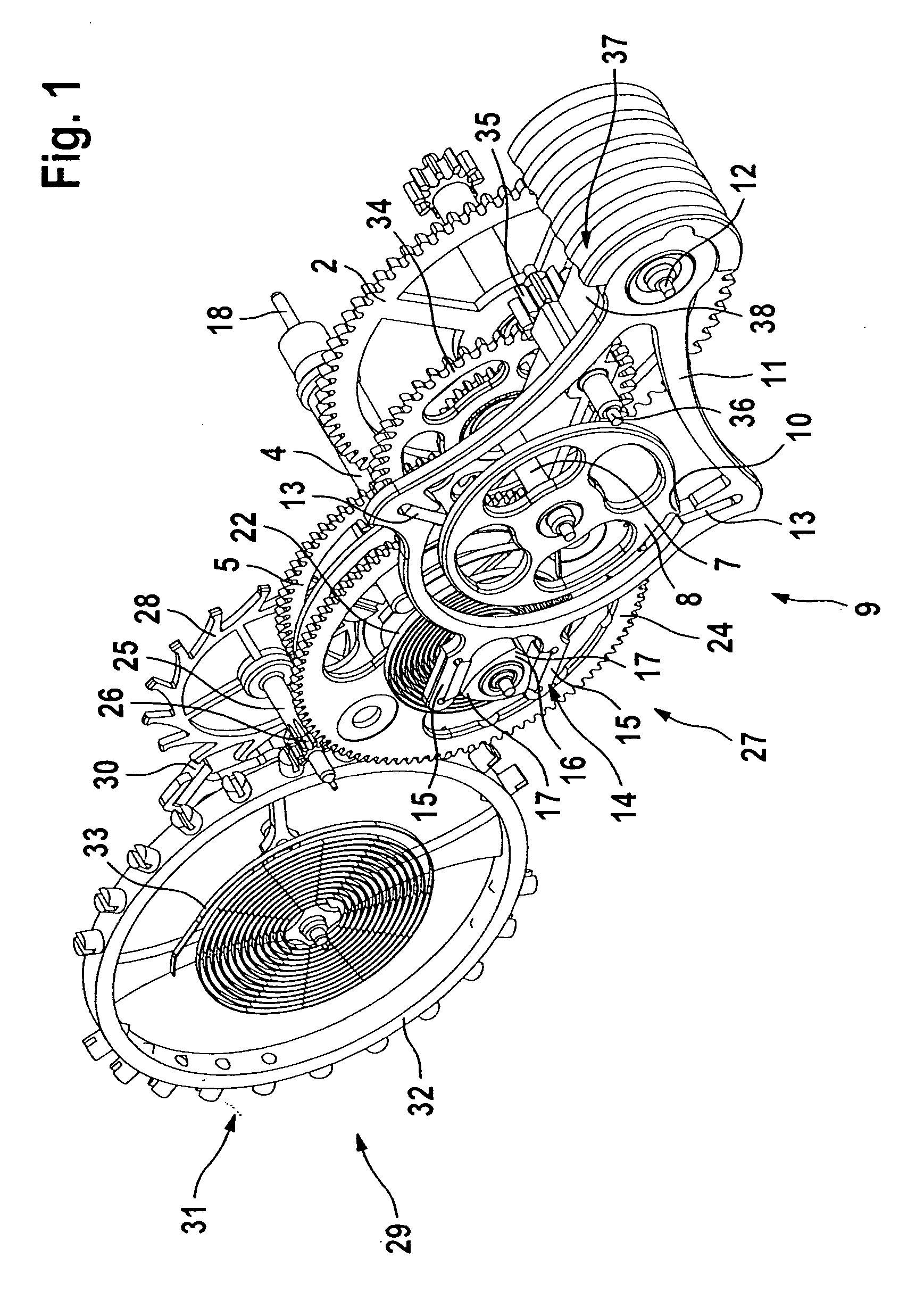
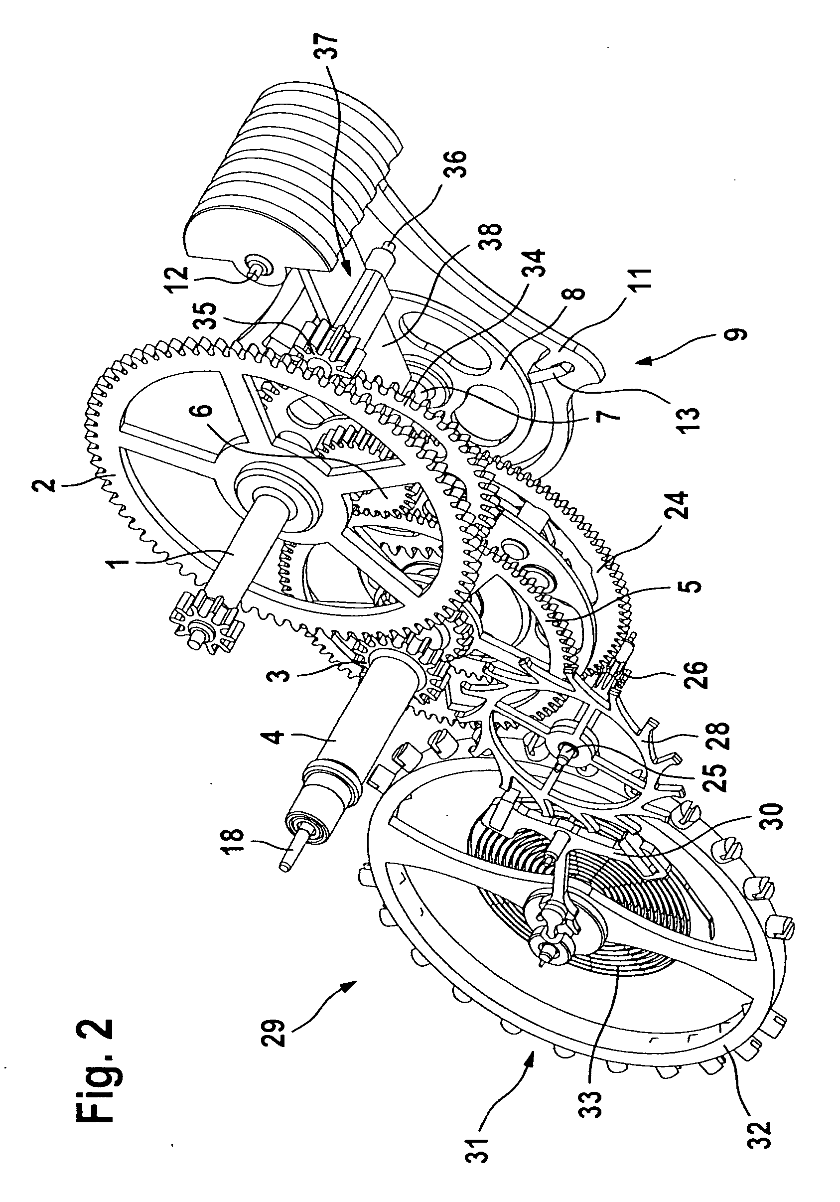
[0032] Referring to FIGS. 2 and 3, a third-wheel shaft 1 is subjected to rotary tensioning by way of a spring barrel 39.

[0033] The third wheel 2, which is fixed on the third-wheel shaft 1, is in engagement with a transmission wheel 3, which is fixed on a 10-seconds tube 4.

[0034] Referring also to FIG. 1, a 10-seconds wheel 5, which is likewise fixed on the 10-seconds tube 4, transmits a rotary movement of the 10-seconds tube 4 to a stop wheel pinion 6, which is fixed on a stop wheel shaft 7, a stop wheel 8 of a switching unit 9 also being fixed on the stop wheel shaft 7.

[0035] The stop wheel 8 has a radially projecting tooth 10 on its circumferential surface.

[0036] Located in the same plane as the stop wheel 8 is a rocker 11, which can be pivoted about an oscillating axis 12 parallel to the axis of rotation of the stop wheel shaft 7.

[0037] The rocker 11 is designed to engage around the stop wheel 8, at a radial distance therefrom, and has two pallets 13 which are located approx...


PUM


Abstract

A timepiece, in particular a wristwatch, includes a constant-force device for acting on an oscillating system, the constant-force device including a switching unit and a tensioning module having a primary spring-energy store and a secondary spring-energy store. A seconds shaft bearing a seconds wheel and a cam plate is driven to rotate constantly by the secondary spring-energy store. The seconds wheel drives the oscillating system, and the cam plate acts on the switching unit for the periodic tensioning of the secondary spring-energy store by the primary spring-energy store.

Description

BACKGROUND OF THE INVENTION [0001] 1. Field of the Invention [0002] The invention relates to a timepiece, in particular a wristwatch with a constant-force device for acting on an oscillating system, the constant force device having a switching unit and a tensioning module. [0003] 2. Description of the Related Art [0004] The switching unit periodically controls tensioning of a secondary spring-energy store of the tensioning module by a spring barrel forming a primary spring-energy store, the periodic control of the switching unit taking place by means of a cam plate which can be driven in a permanently rotatable manner. [0005] By virtue of such constant-force devices, the primary spring-energy store, rather than acting directly on the oscillating system, periodically tensions the secondary spring-energy store, which then acts on the oscillating system. [0006] The level of force acting on the oscillating system is thus, to the greatest possible extent, constant, which results in a hig...

Claims


Application Information

Patent Timeline
IPC IPC(8): G04B23/00G04B25/00G04C21/00
CPCG04B1/225G04B15/10
Inventor GIRARDIN, JOHNNYFORSEY, STEPHEN
Owner LANGE UHREN
Why Eureka
Try Eureka