
Harness installation structure

Inactive Publication Date: 2007-06-28
YAZAKI CORP
View PDF5 Cites 14 Cited by
  • Summary
  • Abstract
  • Description
  • Claims
  • Application Information

AI Technical Summary

Benefits of technology

[0011] With the foregoing in view, it is an object of this invention to provide a harness installation structure of a link-type movable body in which the structure can be simplified, and can be formed into a low-cost design, and besides the number of management points for a surplus length of a wire harness can be reduced, thereby enhancing the reliability of continuous power supply.

Problems solved by technology

However, in the above related harness installation structure of the link-type movable body, in addition to the support arm 71, the pair of link arms 65 and 66 are required, and therefore there has been encountered a problem that the structure is complicated and costly.
And besides, in order to absorb a surplus length of the wire harness 68, the guide rail 63, the slider 64, the caterpillar-type exterior member 69, etc., need to be provided, and this has invited a problem that the structure is further complicated and costly.
Therefore, the design, management, etc., for positively effecting the continuous supply of electric power are very difficult, and besides a space for allowing the bending of the surplus length portion 68a of the wire harness 68 is required, and therefore there has been encountered a problem that the degree of freedom of arrangement of the vehicle body-side parts, etc., may be limited.
Even in the case where the above harness installation structure of the link-type movable body is applied to other movable body than the automobile door, there has been a fear that similar problems as described above arise.

Method used


Image

  • Harness installation structure
  • Harness installation structure
  • Harness installation structure

Examples


Embodiment Construction

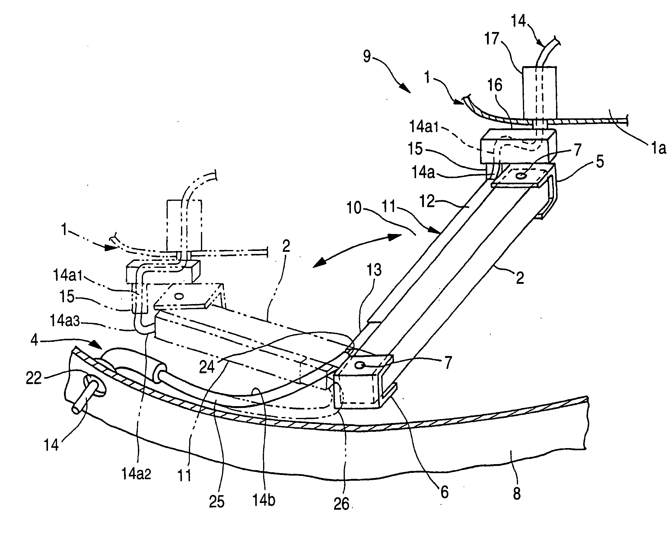
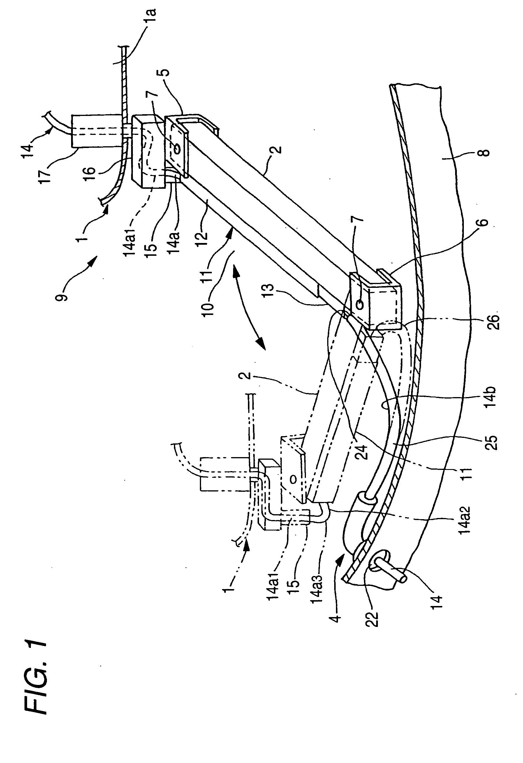
[0045]FIG. 1 shows a rough example of a harness installation structure of a link-type movable body embodying the present invention.

[0046] This link-type movable body is a link-type door 1 of an automobile, and the link-type door 1 is swingably (pivotally) supported on a vehicle body 4 by a link arm 2. The link arm 2 is made of a metallic material such as iron and an aluminum alloy, and has high strength and rigidity. Incidentally, another link arm (not shown) can be provided above the link arm 2 in opposed relation thereto, or another link arm (not shown) can be provided forwardly or rearwardly of the link arm 2 in parallel relation thereto, or besides the link arm 2, a guide rail (not shown) can be used to support the door 1.

[0047] A distal end portion of the link arm 2 is pivotally supported on a door (movable body)-side link bracket 5 by a shaft portion 7, and a proximal end portion of the link arm 2 is pivotally supported on a vehicle body (fixed body)-side link bracket 6 by a...


PUM


Abstract

A harness installation structure includes a link arm that pivotally supports a movable body to a fixed body, a wire harness that is installed to extend from the fixed body to the movable body along the link arm. The wire harness is fixed without looseness at a region between one end of the link arm and the movable body. The wire harness is installed to extend in a bendable manner from the other end of the link arm to the fixed body. While the movable body is moved between an opened position and a closed position, a surplus length of the wire harness is produced at other portion of the wire harness than a movable body-side portion of the wire harness, and the surplus length is absorbed by bending the wire harness.

Description

BACKGROUND OF THE INVENTION [0001] This invention relates to a harness installation structure of a link-type movable body, in which the movable body such for example as a door of an automobile is supported by a link so as to be opened and closed, and a power supply wire harness is installed along the link, and is arranged to extend vertically upwardly, and these upwardly-extending portions are twisted when the door is opened and closed. [0002]FIG. 6 shows one related harness installation structure of a link-type movable body (see JP-A-10-175483 (FIGS. 5 and 9)). [0003] This link-type movable body is a link-type door 62, and the link-type door 62 is swingably supported on a vehicle body 70 by a single support arm 71 of a generally L-shape. The support arm 71 has a high rigidity so as to support the weight of the door 62. [0004] Besides the support arm 71, a pair of front and rear link arms 66 and 65 are provided in parallel relation to each other, and each of the link arms 65 and 66 ...

Claims


Application Information

Patent Timeline
IPC IPC(8): H01R33/00
CPCB60R16/0207H02G11/00
Inventor SATO, KUNIHIKOUEHARA, TAKEHIKO
Owner YAZAKI CORP
Learn More