Continuous hinge for swing door

Inactive Publication Date: 2007-07-05
JOHN STERLING , A CORP OF IL
View PDF10 Cites 20 Cited by
  • Summary
  • Abstract
  • Description
  • Claims
  • Application Information

AI Technical Summary

Benefits of technology

[0020] A bushing is mounted on the projecting arm of the second attachment structure and is disposed in the partially cylindrical channel of the first attachment structure. The bushing has a partially cylindrical exterior surface which (1) is defined around the hinge pivot axis for engag

Problems solved by technology

A variety of problems or potential problems are presented to the designer of a hinge or multiple hinges that are used to mount a door for swinging between a closed position and an open

Method used


Image

  • Continuous hinge for swing door
  • Continuous hinge for swing door
  • Continuous hinge for swing door

Examples


first embodiment

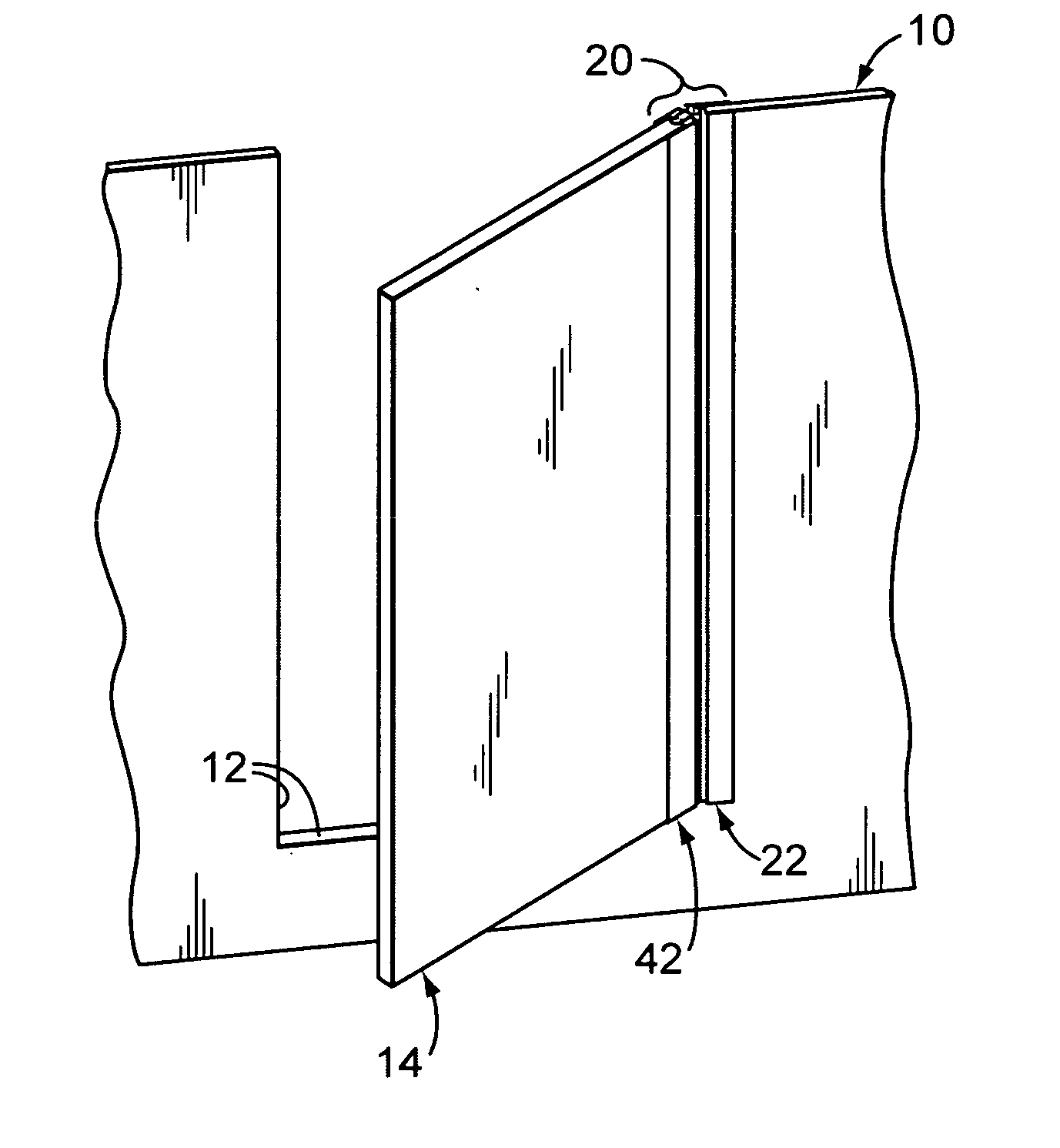
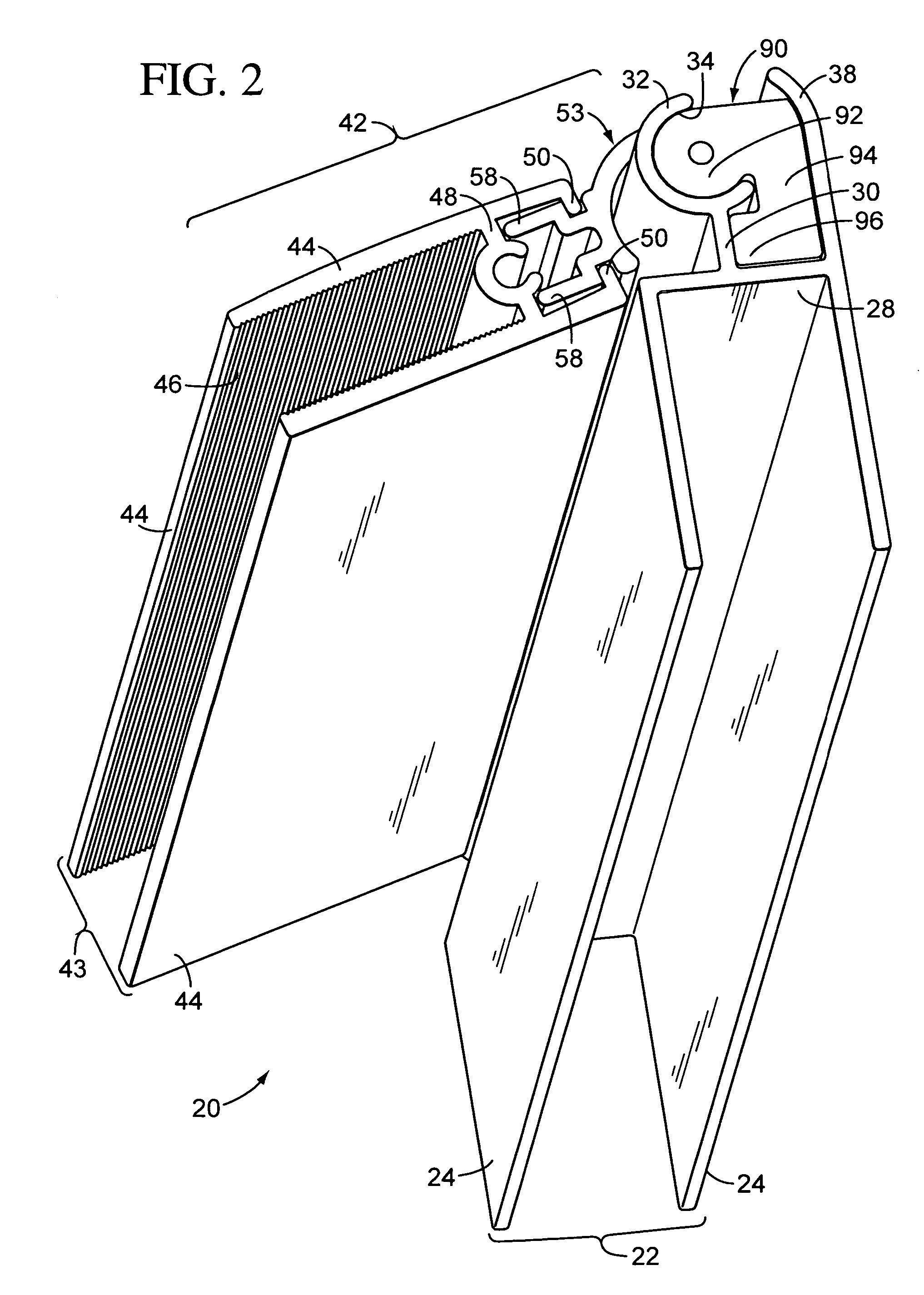
[0043]FIGS. 2, 3, and 6 illustrate the hinge 20 with the wall 10 and door 14 omitted for ease of illustration and for purposes of clearly showing interior details of the hinge components. Further, for ease of illustration in FIGS. 2, 3, and 6, the hinge 20 is shown as having a greatly reduced length or height relative to its width and thickness. It is to be understood that the hinge 20 may have any suitable length, thickness, and width. Further, it is to be understood that the ratio of the hinge length to the thickness of its components or to the width of its components may vary as desired depending upon the particular application for which the hinge 20 is intended.

[0044]FIG. 2 illustrates the hinge 20 at one end of its range of motion. This may be considered either the full open condition or the full closed condition, depending upon how the hinge is installed. However, in a preferred arrangement as illustrated for the first embodiment of the hinge 20, FIG. 2 shows the hinge 20 in a...

second embodiment

[0073]FIG. 10 illustrates the hinge 20A at one end of its range of motion. This may be considered either the full open condition or the full closed condition, depending upon how the hinge 20A is installed. However, in a preferred arrangement illustrated for the hinge 20A in FIGS. 7-10, the hinge 20A is shown in FIG. 10 in a substantially full open condition wherein, the door 14 in FIG. 7 would be pivoted further toward the right to an opening angle of about 110 degrees away from the plane of the wall opening 12A. If the door 14A in FIG. 7 was fully closed (i.e., pivoted to a position in which it is substantially co-planar with the wall opening 12A), then the hinge 20A would have the fully closed orientation as illustrated in FIG. 9.

[0074] As illustrated in FIG. 8, the components of the second embodiment of the hinge 20A include a first attachment structure 22A, a second attachment structure in the form of a multi-piece assembly of a stile 43A, three insert hinges or inserts 53A, thr...


PUM

PropertyMeasurementUnit
Angleaaaaaaaaaa
Lengthaaaaaaaaaa

Abstract

A hinge is provided for connecting a swing door to an adjacent support structure. The hinge includes a first attachment structure for being mounted to either the door or the adjacent support structure and has a partially cylindrical channel defining a longitudinal pivot axis. A second attachment structure is mounted to the other of the door and adjacent support structure, and has a longitudinally extending mounting arm projecting into the partially cylindrical channel of the first attachment structure. A bushing (1) is mounted on the arm of the second attachment structure, (2) is disposed in the partially cylindrical channel of the first attachment structure, and (3) has a partially cylindrical exterior surface which (a) is defined around the pivot axis for engaging the partially cylindrical channel of the first attachment structure, and (b) has a surface hardness that is less than the surface hardness of the partially cylindrical channel.

Description

CROSS REFERENCE TO RELATED APPLICATION(S) [0001] None. STATEMENT REGARDING FEDERALLY SPONSORED RESEARCH OR DEVELOPMENT [0002] None. REFERENCE TO A MICROFICHE APPENDIX [0003] None. TECHNICAL FIELD [0004] This invention relates to a system for mounting a door for pivoting or swinging about an axis. The invention is more particularly related to a hinge, and the hinge is especially suitable for use with a glass door, particularly a glass door for a shower room or other enclosure. BACKGROUND OF THE INVENTION AND TECHNICAL PROBLEMS POSED BY THE PRIOR ART [0005] A variety of problems or potential problems are presented to the designer of a hinge or multiple hinges that are used to mount a door for swinging between a closed position and an open position. [0006] For some types of doors and some types of installations, it would be desirable to provide an improved hinge design to accommodate particular conditions in a cost-effective manner, but also in a manner that is aesthetically pleasing, ...

Claims


Application Information

Patent Timeline
IPC IPC(8): E05D7/00
CPCA47K3/36E05D1/04E05Y2900/114E05Y2800/262E05Y2800/672E05D9/005
Inventor MARSHALL, DANNY RAY
Owner JOHN STERLING , A CORP OF IL
Why Eureka
Try Eureka