Additively manufactured valve assembly

a technology of additive manufacturing and valve assembly, which is applied in the direction of check valves, mechanical equipment, functional valve types, etc., can solve the problems of less reliable, increased cost of valve assemblies, and increased potential leakage or failure points of new potential leakage or failure points

Active Publication Date: 2019-03-21
GENERAL ELECTRIC CO
View PDF7 Cites 12 Cited by
  • Summary
  • Abstract
  • Description
  • Claims
  • Application Information

AI Technical Summary

Problems solved by technology

Thus, such valve assemblies are more expensive due to the increased number of components needed and the assembly time required.
In addition, each joint, fastening point, or other mating surface introduces a new potential leak or failure point.
Therefore, certain conventional valve assemblies cost more, are less reliable, and generally exhibit poor performance.

Method used


Image

  • Additively manufactured valve assembly
  • Additively manufactured valve assembly
  • Additively manufactured valve assembly

Examples


Embodiment Construction

[0022]Reference will now be made in detail to present embodiments of the invention, one or more examples of which are illustrated in the accompanying drawings. The detailed description uses numerical and letter designations to refer to features in the drawings. Like or similar designations in the drawings and description have been used to refer to like or similar parts of the invention. As used herein, the terms “first”, “second”, and “third” may be used interchangeably to distinguish one component from another and are not intended to signify location or importance of the individual components. In addition, terms of approximation, such as “approximately,”“substantially,” or “about,” refer to being within a ten percent margin of error.

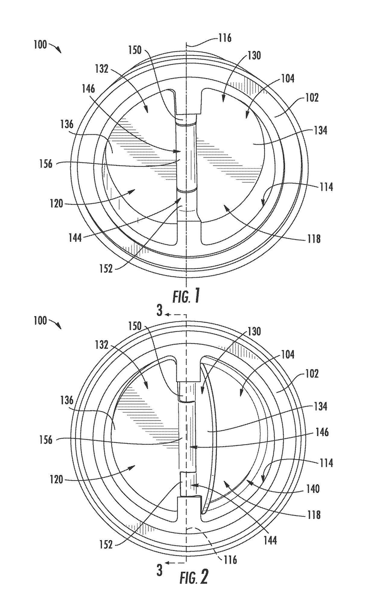
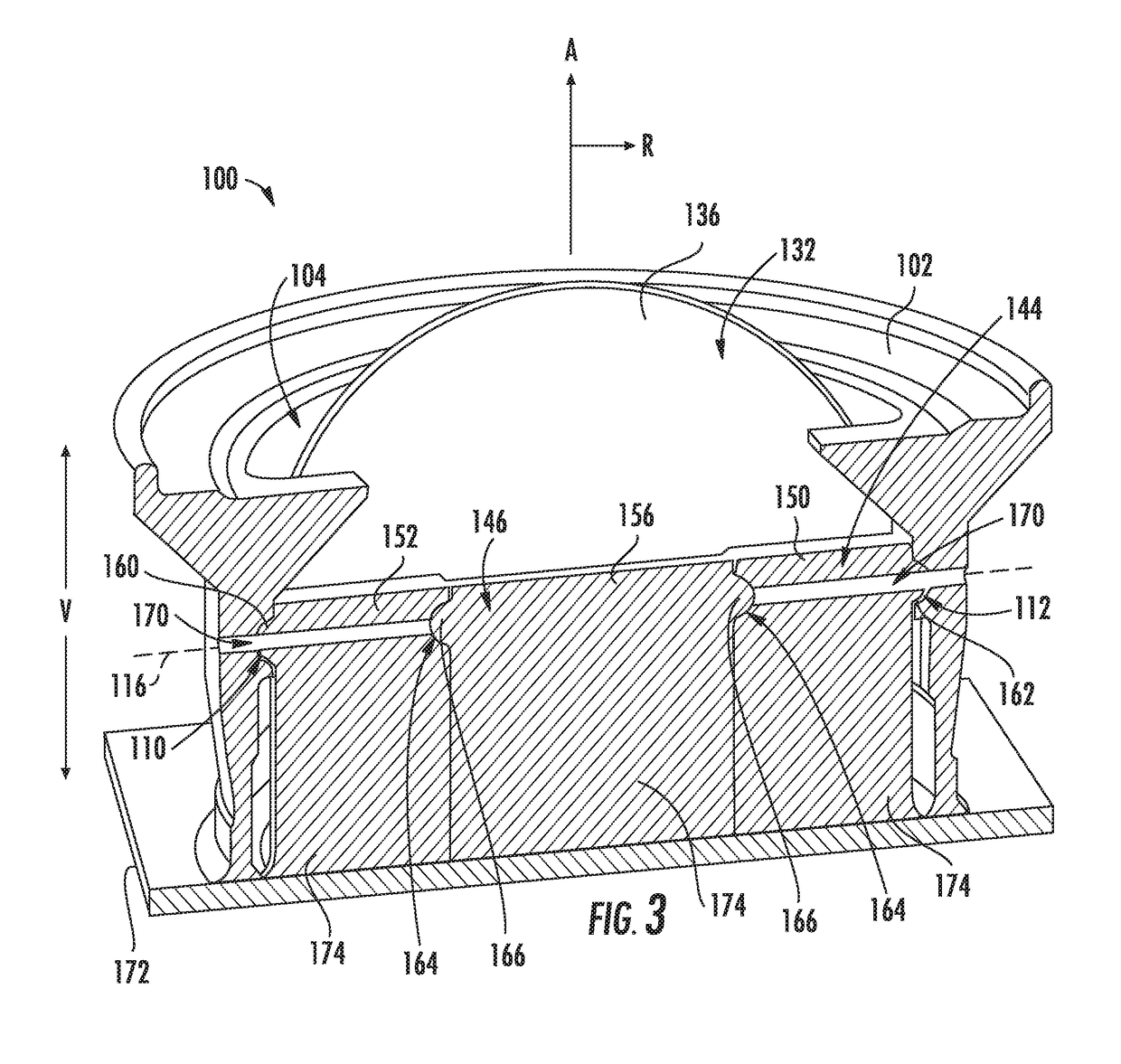
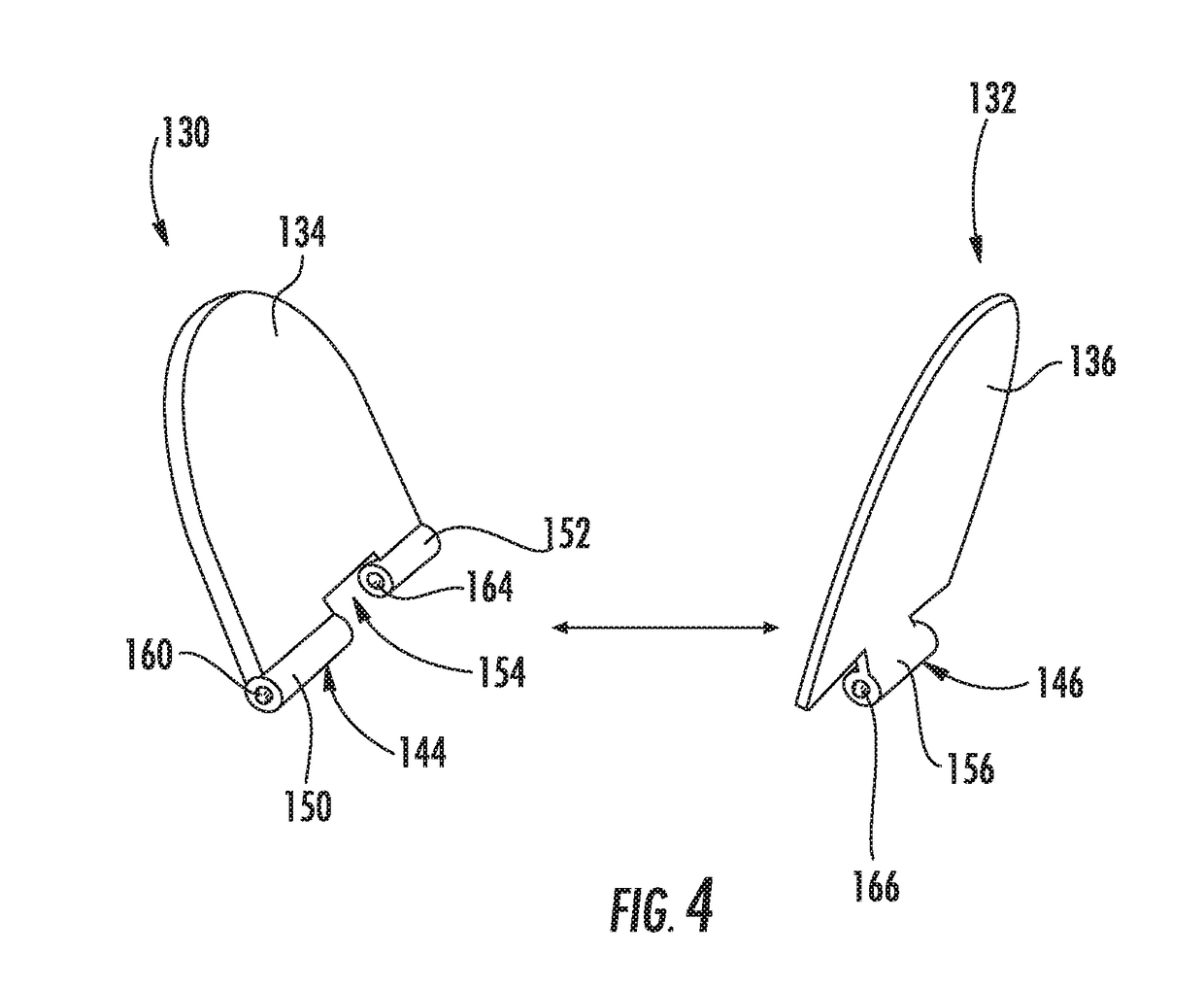
[0023]The present disclosure is generally directed to a valve assembly and a method of additively manufacturing the same. The valve assembly includes a valve housing defining first and second mounting features, such as recessed dimples or protruding bum...


PUM

PropertyMeasurementUnit
thicknessaaaaaaaaaa
thicknessaaaaaaaaaa
energyaaaaaaaaaa

Abstract

A valve assembly and a method of additively manufacturing the same are provided. The valve assembly includes a valve housing defining first and second mounting features, such as recessed dimples or protruding bumps, positioned on opposite sides of a substantially cylindrical channel to define a hinge axis. One or more valve flaps are positioned within the cylindrical channel, each valve flap including a hinge member extending along the hinge axis and defining two or more complementary features or coupling members for engaging either the mounting features of the valve housing or an adjacent hinge member.

Description

FIELD[0001]The present subject matter relates generally to a valve assembly, or more particularly to an additively manufactured valve assembly.BACKGROUND[0002]Valves are commonly used in a variety of industries for regulating, directing, or controlling a flow of fluid. Valves typically include a housing that defines a passageway providing fluid communication between two or more fluid conduits. A body positioned within the passageway may be manipulated to permit, restrict, or otherwise regulate a flow of fluid through the passageway.[0003]For example, a conventional “flapper” valve may define a passageway and include a hinge pin extending through a center of the passageway. One or more valve flaps are rotatably mounted to the hinge pin and are configured for pivoting between an open and a closed position. More specifically, the valve flaps may be configured for pivoting toward an open position when fluid flows in a forward direction and may pivot back to a closed position when fluid ...

Claims


Application Information

Patent Timeline
Patent Type & Authority Applications(United States)
IPC IPC(8): F16K1/20F16K1/16B33Y10/00B33Y80/00B22F3/105
CPCF16K1/2028F16K1/165B33Y10/00B33Y80/00B22F3/1055F16K15/038F16K15/03B22F5/008B22F2999/00Y02P10/25B22F10/28B22F10/66B22F10/40
Inventor DUNHAM, EARL NEALAKWARA, AIGBEDIONWOLFE, JARED MATTHEW
Owner GENERAL ELECTRIC CO
Why Eureka
Try Eureka