More electric aircraft starter-generator multi-speed transmission system

Inactive Publication Date: 2007-07-05
HONEYWELL INT INC
View PDF39 Cites 176 Cited by
  • Summary
  • Abstract
  • Description
  • Claims
  • Application Information

AI Technical Summary

Benefits of technology

[0006] The present invention provides a multi-speed transmission between the high pressure and low pressure turbines in a multi-spool gas turbine engine that reduces the operating speed range f

Problems solved by technology

Although these architectures are generally safe, robust, and reliable, the architectures may suffer certain drawbacks.
For example, high shaft power extraction demand can negatively impact engine compressor surge margin.
This solution, however, can increase both the fue

Method used


Image

  • More electric aircraft starter-generator multi-speed transmission system
  • More electric aircraft starter-generator multi-speed transmission system
  • More electric aircraft starter-generator multi-speed transmission system

Examples


Embodiment Construction

[0011] Before proceeding with the detailed description, it is to be appreciated that the following detailed description is merely exemplary in nature and is not intended to limit the invention or the application and uses of the invention. In this regard, it is to be additionally appreciated that the described embodiment is not limited to use in conjunction with a particular type of turbine engine. Hence, although the present embodiment is, for convenience of explanation, depicted and described as being implemented in a multi-spool gas turbine jet engine, it will be appreciated that it can be implemented in various other types of turbines, and in various other systems and environments. Furthermore, there is no intention to be bound by any theory presented in the preceding background or the following detailed description.

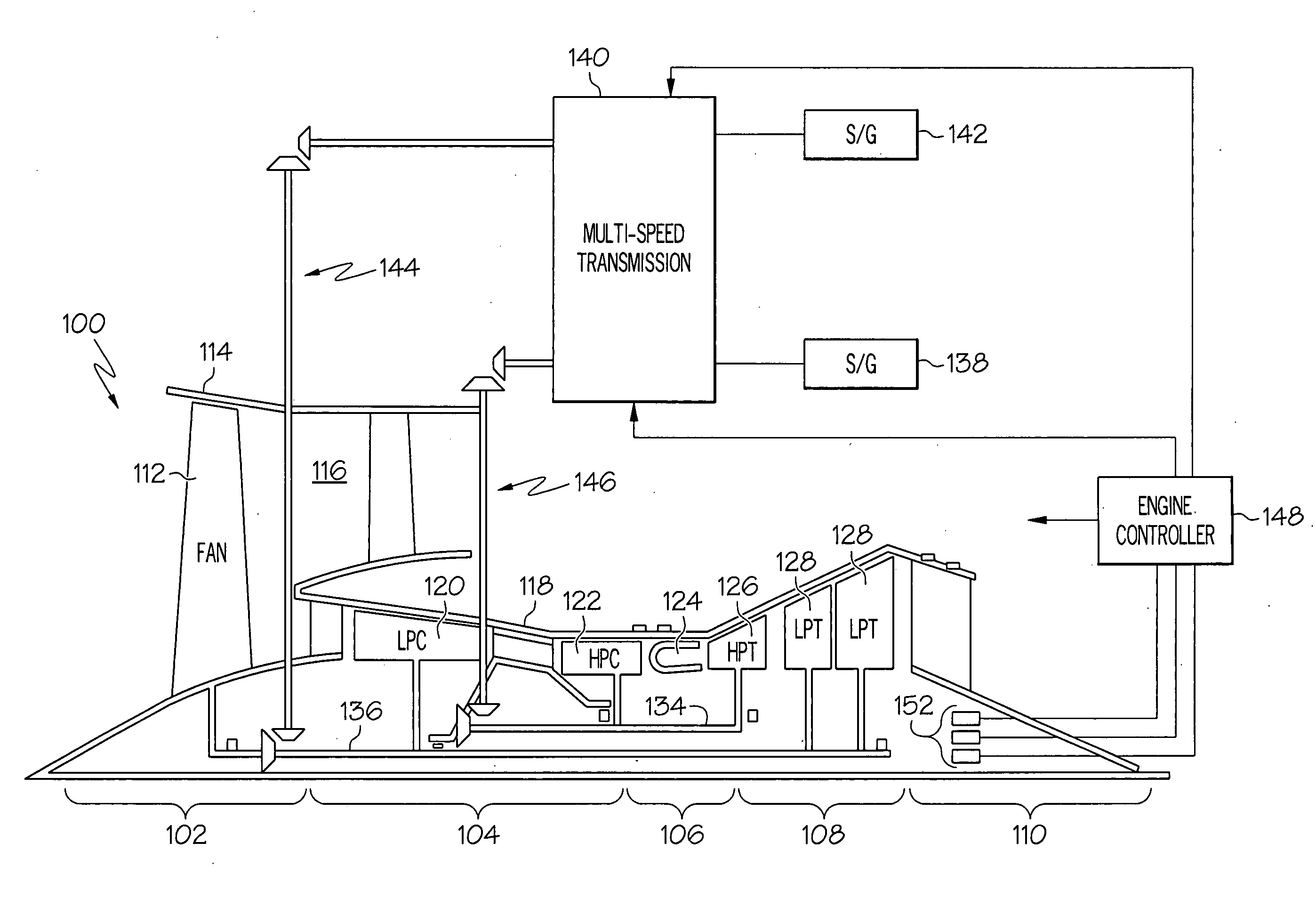
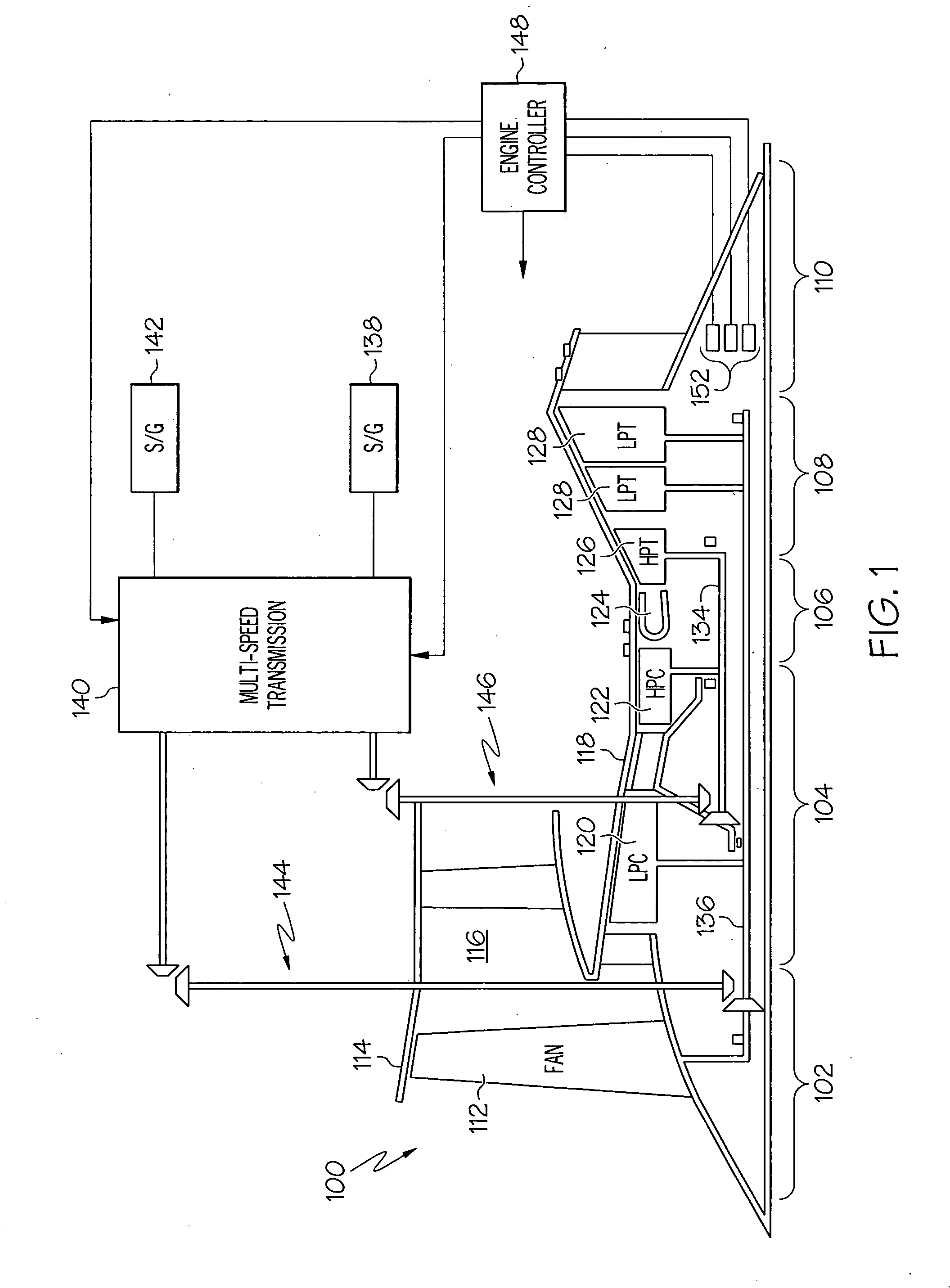
[0012] A simplified representation of an exemplary multi-spool turbofan gas turbine jet engine 100 is depicted in FIG. 1, and includes an intake section 102, a compr...


PUM


Abstract

A turbofan gas turbine propulsion engine includes a multi-speed transmission between the high pressure and low pressure turbines and associated high pressure and low pressure starter-generators. The multi-speed transmission reduces the operating speed range from the low pressure turbine to its associated starter-generator, and is configurable to allow the starter-generator associated with the low pressure turbine to supply starting torque to the engine.

Description

TECHNICAL FIELD [0001] The present invention relates to turbofan gas turbine propulsion engines and, more particularly, to a system for extracting additional power from the low pressure turbine in a turbofan gas turbine propulsion engine, and allowing a starter-generator that is normally driven by a low pressure turbine to supply starting torque to the turbofan gas turbine propulsion engine. BACKGROUND [0002] Aircraft main propulsion engines not only generate propulsion thrust for the aircraft, but in many instances may also be used to drive various other rotating components such as, for example, generators, compressors, and pumps, to thereby supply electrical, pneumatic, and / or hydraulic power. In multi-spool turbofan gas turbine engines, this is accomplished via a plurality of turbines. In particular, each turbine receives a flow of combusted gas from a combustor and, in response, generates shaft power that is used to drive one or more of these rotational components, via a plurali...

Claims


Application Information

Patent Timeline
IPC IPC(8): F02C7/36
CPCF02K3/06F02C7/36F16H3/54F16H2200/0034F16H2200/2005F16H2200/2035F16H2200/2066F16H2200/2082F16H37/0826
Inventor GAINES, LOUIE T.AUER, PETER J.LANE, GLENN H.WISSINGER, JAMES A.
Owner HONEYWELL INT INC
Why Eureka
Try Eureka