Tracked vehicle electromechanical composite transmission device and composite transmission control method thereof

An electromechanical compound transmission and vehicle technology, applied in the direction of control drive, control device, vehicle components, etc., can solve the problems of high motor performance requirements, difficulty in maintaining driving linearity, inconsistent output speed of motors on both sides, etc., to reduce torque and Speed ​​adjustment range, reduced difficulty, good straight-line effect

Pending Publication Date: 2020-04-10
BEIJING INSTITUTE OF TECHNOLOGYGY
View PDF0 Cites 0 Cited by
  • Summary
  • Abstract
  • Description
  • Claims
  • Application Information

AI Technical Summary

Problems solved by technology

[0004] The purpose of the embodiment of the present invention is to provide an electromechanical compound transmission device for a tracked vehicle to solve the problem that the existing tracked vehicle adopts a drive system independently driven by double-sided motors. When driving in a straight line, the output speeds of the motors on both sides are inconsistent and it is difficult to maintain the straightness of driving. The problem
[0005] Another object of the embodiment of the present invention is to provide a compound transmission control method for a tracked vehicle electromechanical compound transmission device, to solve the problem that the existing tracked vehicle adopts a drive system in the form of independent drive of double-sided motors. high performance issues

Method used


Image

  • Tracked vehicle electromechanical composite transmission device and composite transmission control method thereof
  • Tracked vehicle electromechanical composite transmission device and composite transmission control method thereof

Examples


Embodiment Construction

[0025] The following will clearly and completely describe the technical solutions in the embodiments of the present invention with reference to the accompanying drawings in the embodiments of the present invention. Obviously, the described embodiments are only some, not all, embodiments of the present invention. Based on the embodiments of the present invention, all other embodiments obtained by persons of ordinary skill in the art without making creative efforts belong to the protection scope of the present invention.

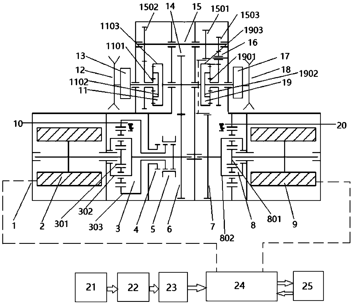
[0026]Mechatronic compound transmissions for tracked vehicles, such as figure 2 As shown, it includes the transmission box housing 1 and the left driving wheel 12, the left side transmission 13, the right side transmission 17 and the right driving wheel 18 positioned at the outside of the transmission box housing 1, and the transmission box housing 1 is provided with a direct drive motor 2. Straight driving speed reduction row 3, steering speed reduction row ...


PUM


Abstract

The invention discloses a tracked vehicle electromechanical composite transmission device and a composite transmission control method thereof. The tracked vehicle electromechanical composite transmission device comprises a transmission case shell, wherein the transmission case shell is internally provided with a straight driving motor, and the straight driving motor is mechanically connected witha straight driving gear A through a straight driving deceleration row; the straight driving gear A is meshed with a straight driving gear B, a left planet row is arranged on the left side of the straight driving gear B, a right planet row is arranged on the right side of the straight driving gear B, and the straight driving gear B, the left planet row and the right planet row are fixed to the sametransmission shaft; the left planet row is mechanically connected with a left side transmission input end located outside the transmission case shell, and a left side transmission output end is mechanically connected with a left driving wheel; the right planet row is mechanically connected with a right side transmission input end located outside the transmission case shell, a right side transmission output end is mechanically connected with a right driving wheel, and the transmission case shell is further internally provided a steering motor arranged opposite to the straight driving motor. The problem that it is difficult to keep straight driving due to inconsistent output rotating speed of motors on the two sides of the tracked vehicle is solved.

Description

technical field [0001] The invention belongs to the technical field of power assembly components, and relates to an electromechanical compound transmission device of a crawler vehicle and a compound transmission control method thereof. Background technique [0002] With the development of core key component technologies such as power electronics technology, control technology, high-power permanent magnet synchronous motors, and high-performance batteries, there are more and more researches on the application of electric drives in tracked vehicles. Tracked vehicles are generally heavier than wheeled vehicles, have narrower space on the vehicle, and have more transmission functions. Therefore, the requirements for power indicators, power-to-volume ratio, and power-to-weight ratio of components such as motors and batteries are very high. How to organically integrate the motor and machinery under the premise of the limited technical level of the components, meet the layout requi...

Claims


Application Information

Patent Timeline
Patent Type & Authority Applications(China)
IPC IPC(8): B60K17/12B60L15/20B62D11/06
CPCB60K17/12B60L15/20B62D11/06Y02T10/72
Inventor 李雪原王益平
Owner BEIJING INSTITUTE OF TECHNOLOGYGY
Why Eureka
Try Eureka