Hydraulic speed governing positive wagon

A speed regulation and hydraulic technology, applied in the direction of fluid transmission, belt/chain/gear, mechanical equipment, etc., can solve the problems such as the inability to regulate the speed of the hydraulic front box, the increase of drilling costs and costs, and the repair and replacement of drilling stops. Achieve the effect of reducing drilling costs and costs, wide application range and energy saving

Inactive Publication Date: 2008-01-30
王虎财
View PDF0 Cites 0 Cited by
  • Summary
  • Abstract
  • Description
  • Claims
  • Application Information

AI Technical Summary

Problems solved by technology

First, because the hydraulic positive carriage cannot adjust the speed, the coupler always works at a high speed of about 1500 rpm, resulting in serious heat generation of the coupler and a high failure rate, requiring frequent drilling repairs and replacements
The second is that the speed of the hydraulic positive carriage cannot be adjusted, so that the speed of the drilling rig remains unchanged under any power condition, and the high-power operation causes energy waste and large power loss, which increases the drilling cost and cost, and seriously affects the work efficiency.

Method used


Image

  • Hydraulic speed governing positive wagon
  • Hydraulic speed governing positive wagon
  • Hydraulic speed governing positive wagon

Examples


Embodiment Construction

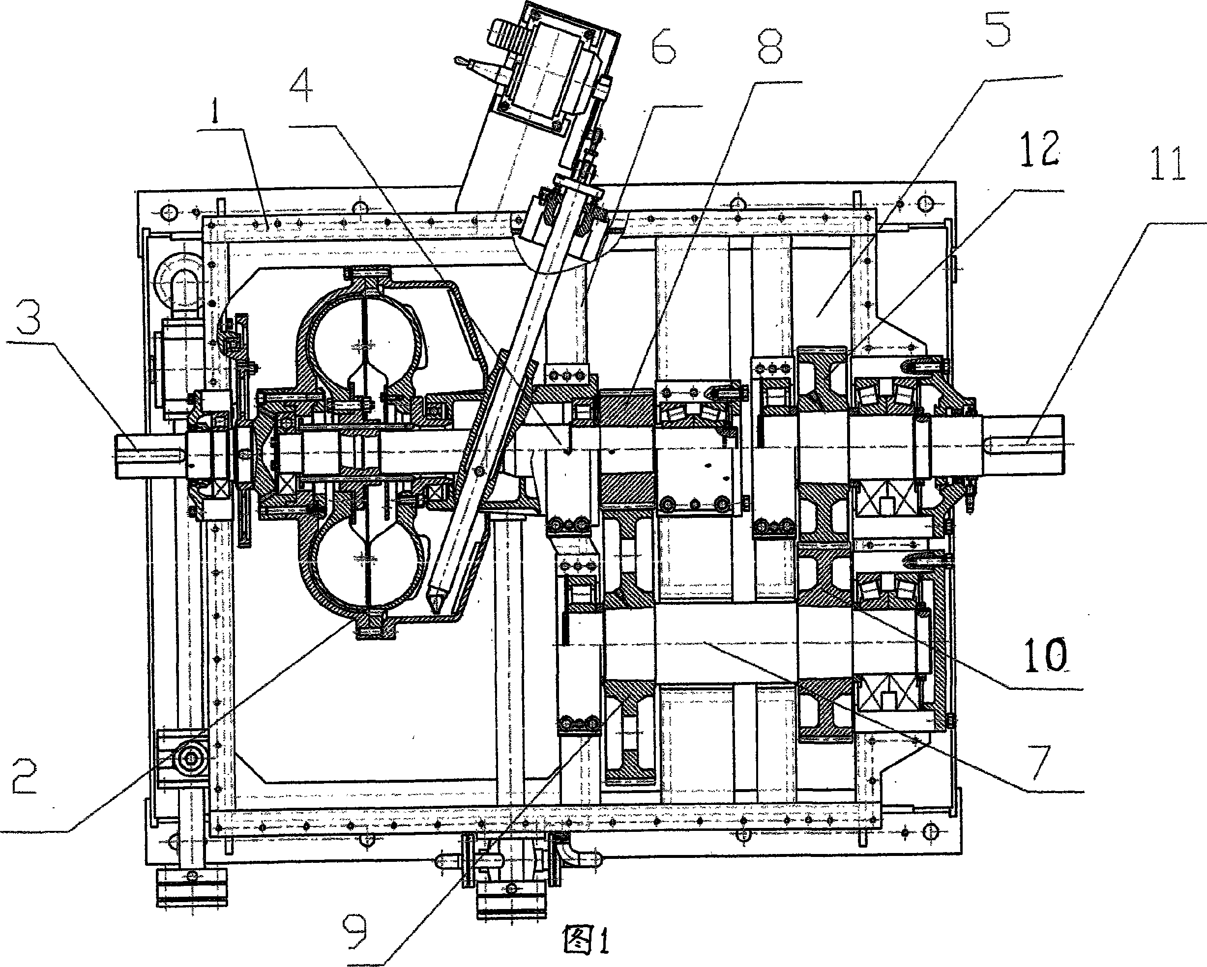
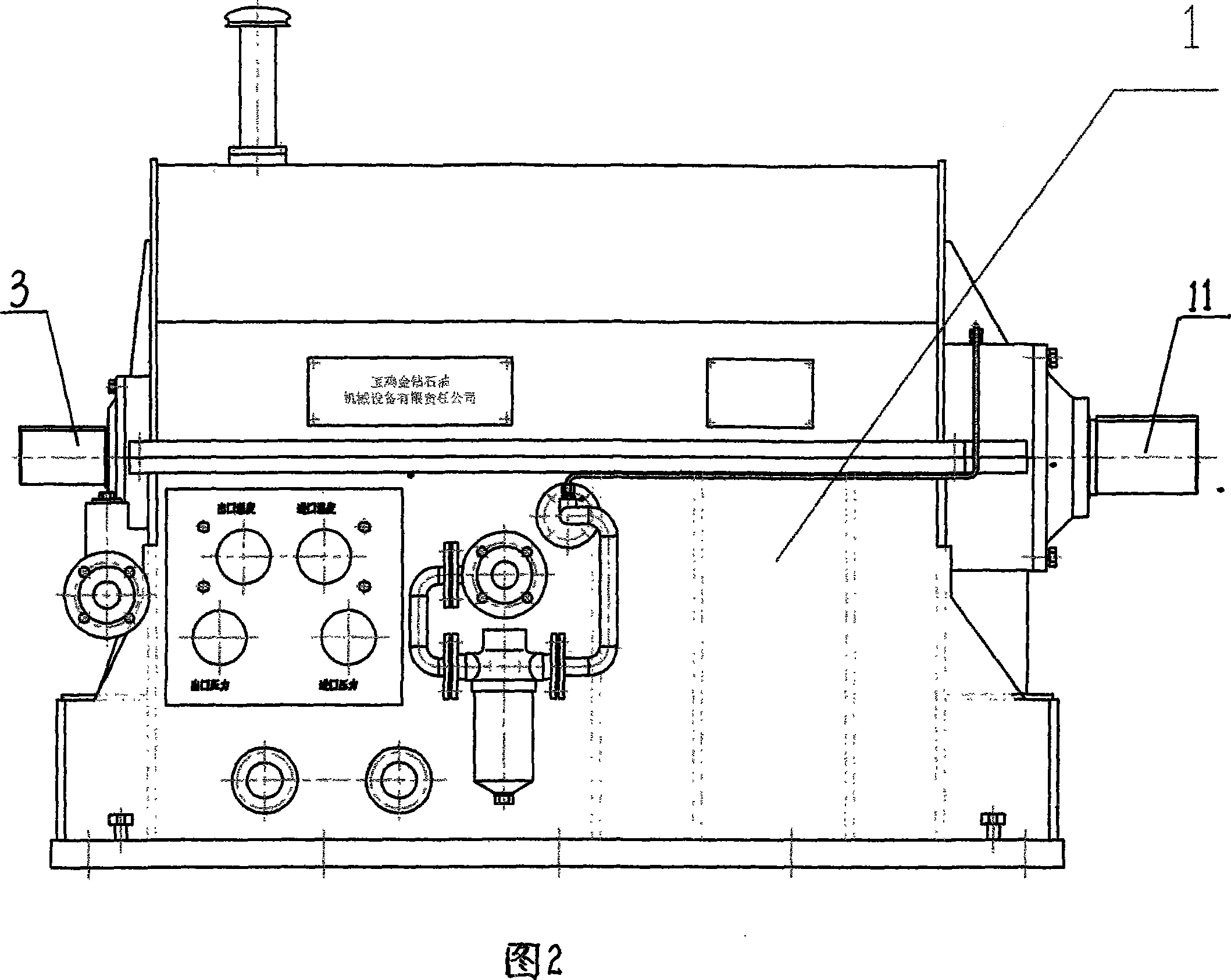
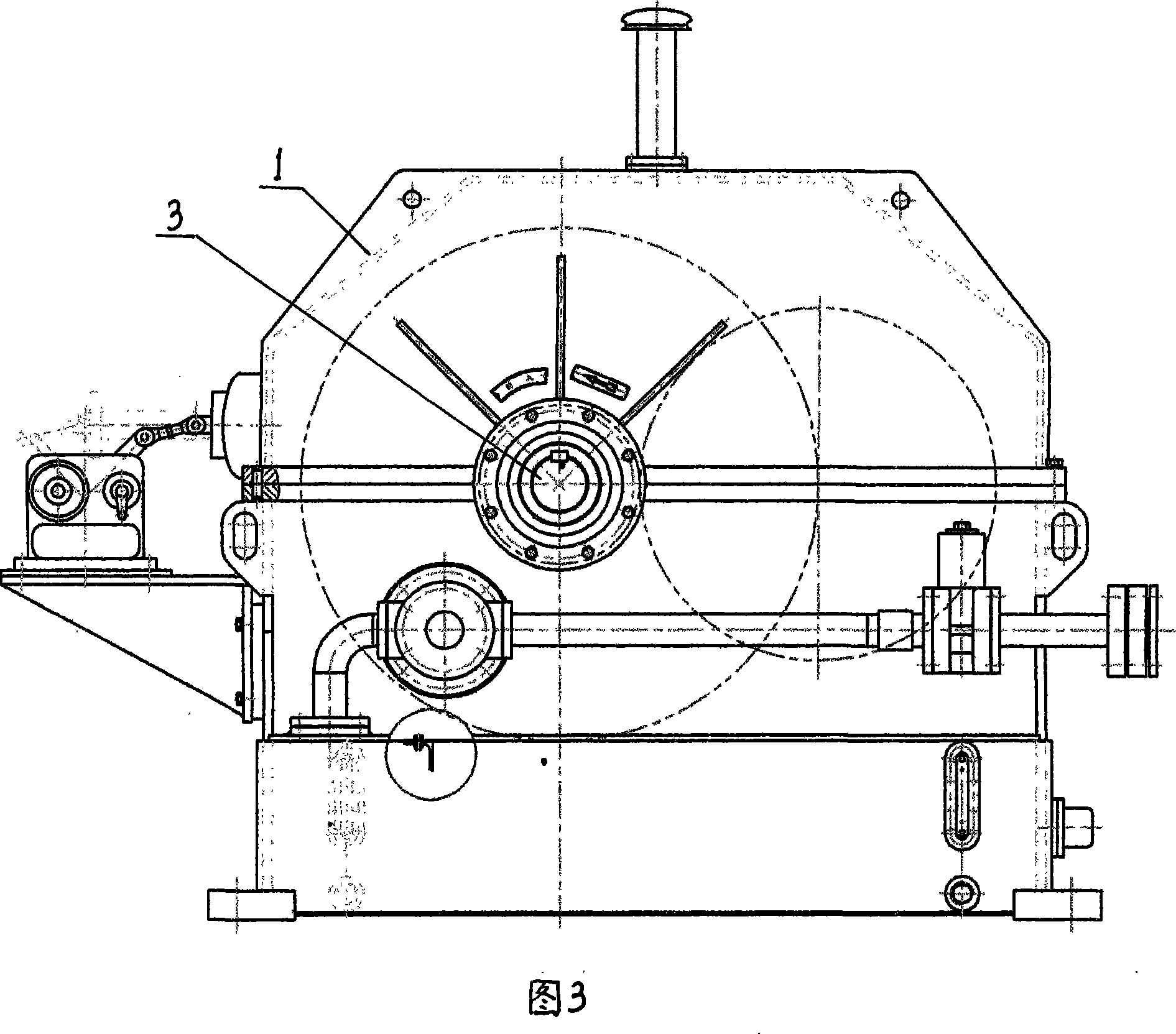
[0017] The first embodiment of the present invention is described in conjunction with accompanying drawings 1, 2, 3.

[0018] A horizontal hydraulic speed regulating front box, including a box body (1), the box body (1) is divided into two parts by a partition (6), and the left part of the box body (1) is a hydraulic coupling ( 2), the right part of the box body (1) is the gear reduction box (5), the power input shaft (3) of the fluid coupling (2) is connected with the main shaft of the power machine, and the power output shaft of the gear reduction box (5) (11) is connected with the working machine, the power output shaft (4) of the fluid coupling (2) is fixed with a small gear (8), and the power input shaft (7) of the gear reduction box (5) is fixed with a large gear ( 9) and the steering gear (10), the power output shaft (11) of the gear reduction box (5) is fixed with the steering gear (12), the pinion (8) meshes with the bull gear (9), and the steering gear (10) Mesh wit...


PUM


Abstract

The invention relates to a hydraulic speeding gear box. The left part of a box body (1) is a hydraulic coupler (2), the right part is a gear decelerating box (5); the power input shaft (3) of the hydraulic coupler (2) is connected with a main shaft of a power machine, the power output shaft (11) of the gear decelerating box (5) is connected with a working machine; a small gear (8) is fixed on the power output shaft (4) of the hydraulic coupler (2), a large gear (9) and a steering gear (10) are arranged on the power input shaft (7) of the gear decelerating box (5), and a steering gear (12) is fixed on the power output shaft (11) of the gear decelerating box (5); wherein, the small gear (8) is engaged with the large gear (9), and the steering gear (10) is engaged with the steering gear (12). The invention combines the hydraulic coupler, the speeding box and the speeding gear into a whole, not only realizes hydraulic transmission, reactive speeding and decelerating, but also ensures that the power machine coincides with the transmission of the working machine. The invention is mainly applied to the power machinery of all types of oil chain drillers.

Description

technical field [0001] The invention relates to a hydraulically adjustable positive carriage. Background technique [0002] At present, most domestic oil chain drilling rig power units use hydraulic positive carriages to adjust the steering of the power machine and the working machine, so that the steering of the power machine is consistent with the steering of the working machine. First, because the hydraulic positive carriage cannot adjust the speed, the coupler always works at a high speed of about 1500 r / min, resulting in severe heat generation of the coupler and a high failure rate, requiring frequent drilling repairs and replacements. The 2nd, because the hydraulic positive carriage can not adjust the speed, so that the drilling machine rotates at a constant speed under any power situation, high-power operation causes energy waste and large power loss, increases the drilling cost and cost, and the work efficiency is also seriously affected. Contents of the invention ...

Claims


Application Information

Patent Timeline
Patent Type & Authority Applications(China)
IPC IPC(8): F16H47/00
Inventor 王虎财王芳
Owner 王虎财
Why Eureka
Try Eureka