Handbrake having input load limiter

a technology of load limiter and handbrake, which is applied in the direction of mechanical control devices, process and machine control, instruments, etc., can solve the problems of unwanted movement of the car, damage or failure of the brake rigging, and many more instances of handbrake over-application

Active Publication Date: 2007-07-05
AMSTED RAIL CO INC
View PDF9 Cites 24 Cited by
  • Summary
  • Abstract
  • Description
  • Claims
  • Application Information

AI Technical Summary

Benefits of technology

[0011] The second handle may be rotated to cause the second pawl to disengage from the second ratchet wheel allowing the first shaft to rotate in the second opposite direction. The second pawl is releasably maintained in the disengaged position so that the torque applied to the railway car brake rigging is fully released. The second pawl may be biased back into engagement with the second ratchet wheel by rotating the first handle to prevent the first shaft from rotating in the second opposite direction.

Problems solved by technology

An under applied brake can result in unwanted movement of the car, for example a runaway car.
On the opposite end of the spectrum, an over applied brake may result in damage or failure to the brake rigging.
This lowered threshold can result in many more instances when the handbrake is over applied.
When the brake is to be fully applied with 125 pounds, there exists the possibility of the handbrake being under applied.

Method used


Image

  • Handbrake having input load limiter
  • Handbrake having input load limiter
  • Handbrake having input load limiter

Examples


Embodiment Construction

[0021] Reference will now be made in detail to presently preferred embodiments of the invention, one or more examples of which are illustrated in the accompanying drawings. Each example is provided by way of explanation of the invention, not limitation of the invention. In fact, it will be apparent to those skilled in the art that modifications and variations can be made in the present invention without departing from the scope and spirit thereof. For instance, features illustrated or described as part of one embodiment may be used on another embodiment to yield a still further embodiment. Thus, it is intended that the present invention covers such modifications and variations as come within the scope of the appended claims and their equivalents.

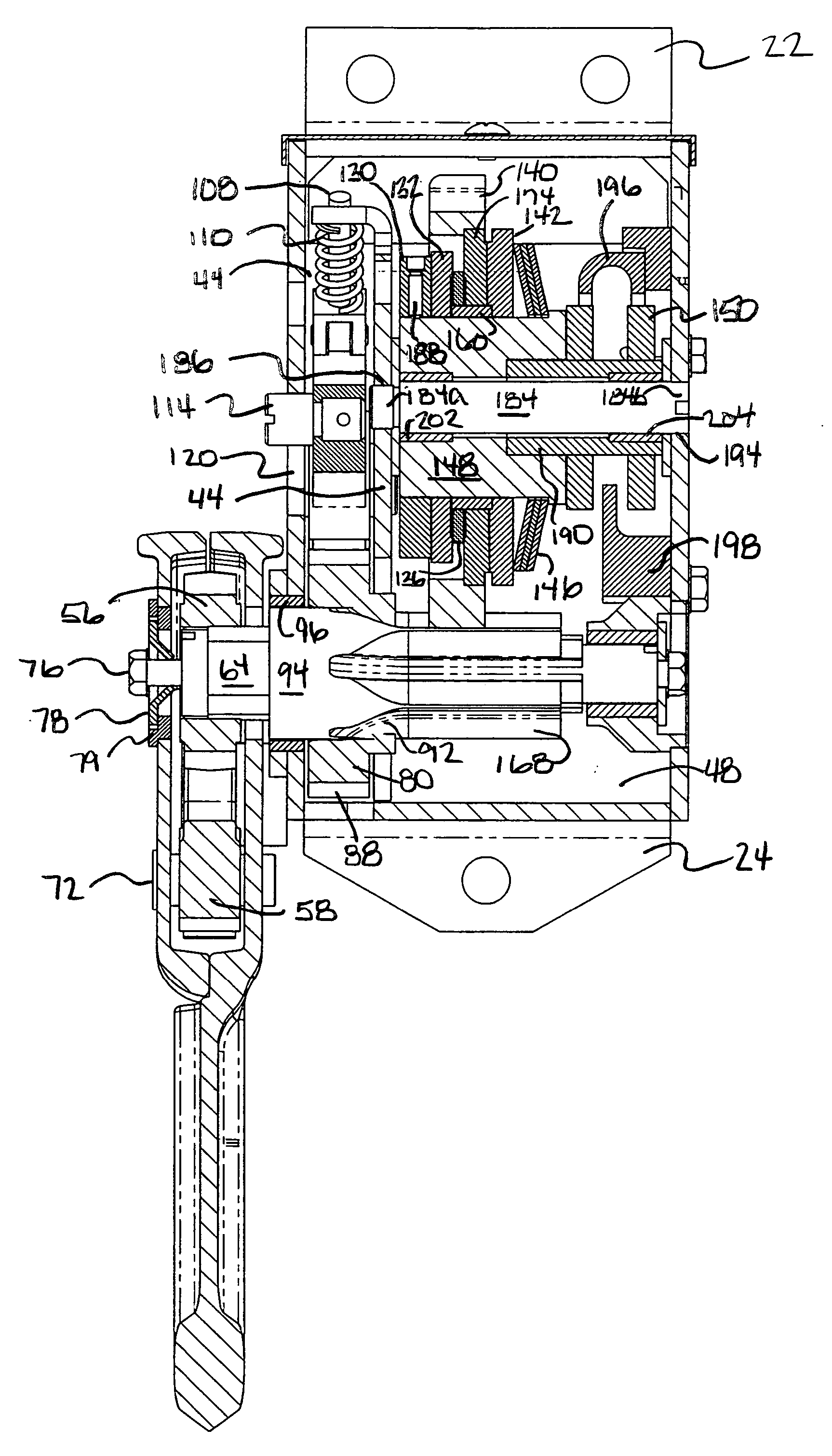
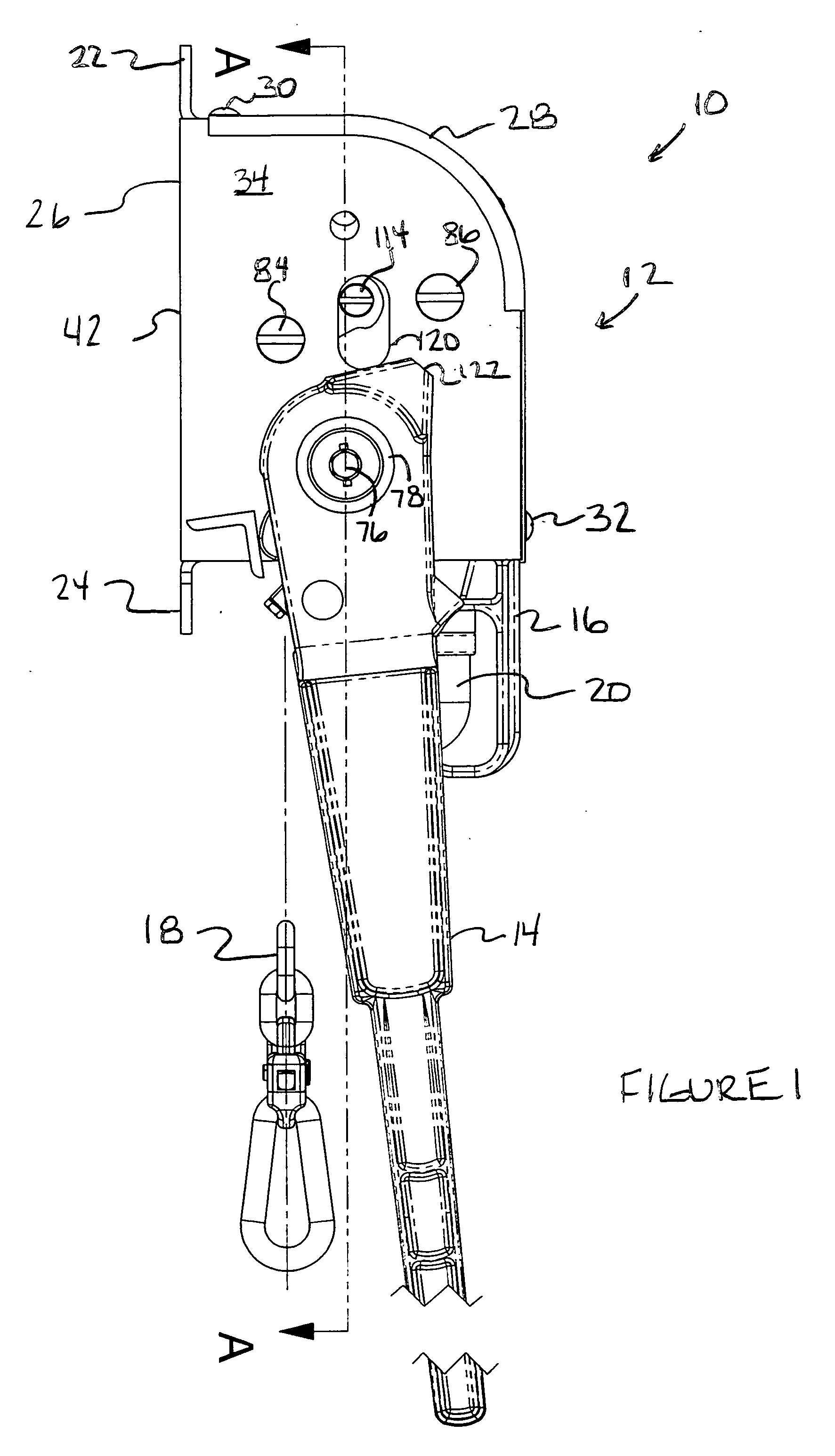
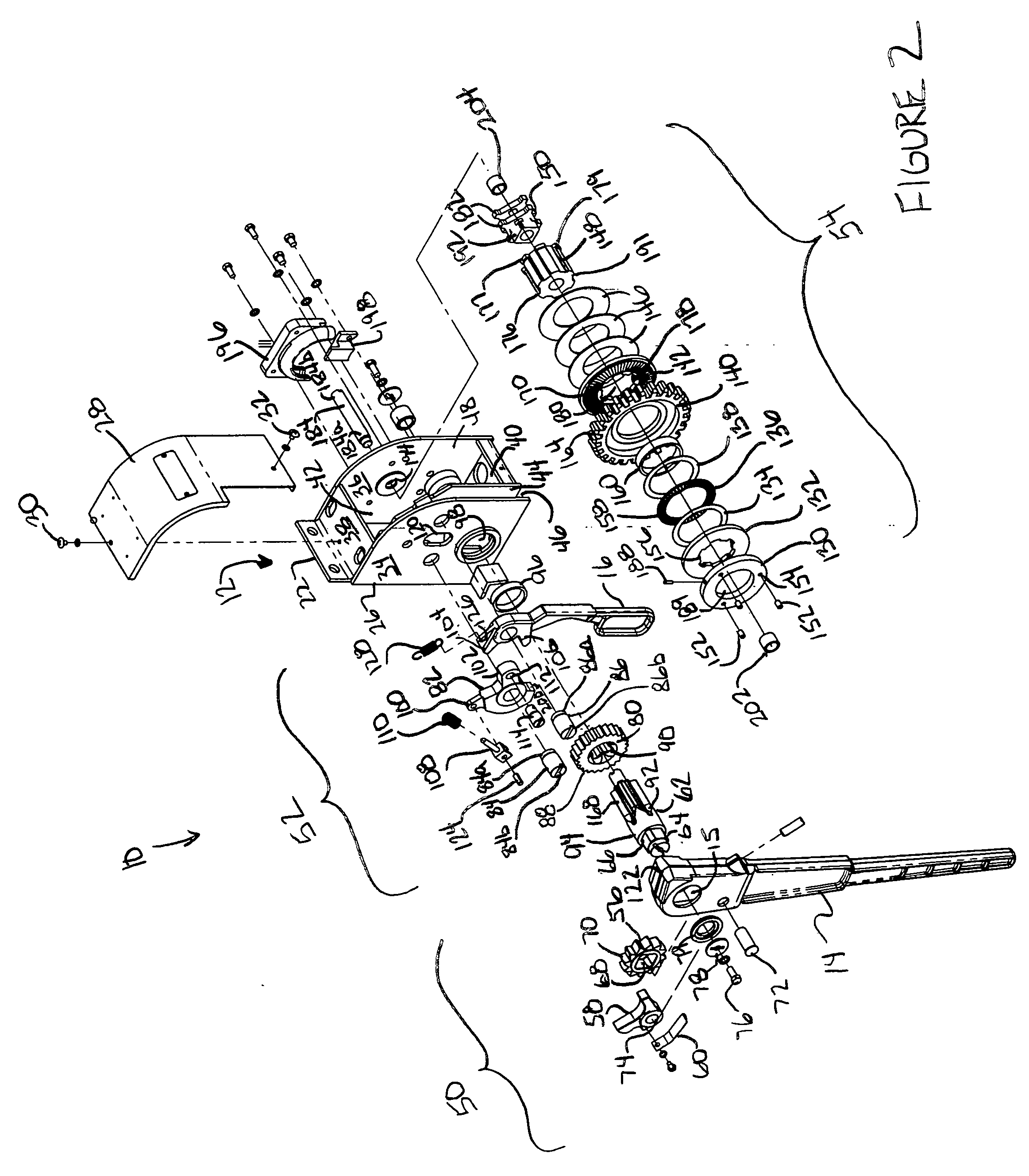
[0022] Referring to FIG. 1 a handbrake mechanism 10 generally comprises a housing 12, a handle 14 rotatably coupled to a gear mechanism (not shown), a quick release handle 16 operatively connected to the gear mechanism, a chain 18 coupled t...


PUM


Abstract

A brake mechanism for activating the brake rigging of a railway car, the brake mechanism comprising a shaft having axial splines formed on one end thereof, a handle rotatably coupled to the shaft so that the handle is rotationally fixed to the shaft in a first direction and rotates relative to the shaft in an opposite second direction. A first gear is connected to the railway car brake rigging, a second gear is in operative engagement with the shaft splines, and a clutch is operatively disposed between the first gear and the second gear, the clutch having a coupler for rotationally coupling the first gear and the second gear and at least one spring operatively disposed intermediate the first gear and the second gear for biasing the coupler into engagement with the second gear. The coupler is moveable between a first position in which the first gear is rotationally coupled to the second gear, and a second position in which the first gear rotates with respect to the second gear.

Description

CLAIM OF PRIORITY [0001] This application claims priority to U.S. Provisional Patent Application No. 60 / 718,292, filed Sep. 19, 2005, the entire disclosure of which is incorporated by reference herein.BACKGROUND OF THE INVENTION [0002] This invention relates to hand operable brake mechanisms and particularly, to a handbrake load limiter for railway cars. [0003] Railway car handbrake mechanisms are well known and may include a rotatable wheel or lever that provides upward tension on a chain that is secured at its distal end to a brake rigging of the railway car. Sufficient force must be applied on the brake shoes of the railway car to releasably secure the wheels in a locked position to prevent the railway car from moving. An under applied brake can result in unwanted movement of the car, for example a runaway car. On the opposite end of the spectrum, an over applied brake may result in damage or failure to the brake rigging. [0004] Previously, it has been industry standard to apply ...

Claims


Application Information

Patent Timeline
Patent Type & Authority Applications(United States)
IPC IPC(8): B61H13/00
CPCY10T74/2048B61H13/02
Inventor MICHEL, MARKSHEPHERD, ROBERT
Owner AMSTED RAIL CO INC
Why Eureka
Try Eureka