Recording disk drive capable of suppressing vibration of flexible printed circuit board

a flexible printed circuit board and recording disk technology, applied in the direction of laminating printed circuit boards, dielectric characteristics, instruments, etc., can solve the problems of insufficient positioning accuracy of the first particularly limited displacement of the second flexible printed circuit board, etc., to achieve the effect of suppressing vibration of the flexible printed circuit board and higher accuracy

Inactive Publication Date: 2007-07-05
FUJITSU LTD
View PDF8 Cites 24 Cited by
  • Summary
  • Abstract
  • Description
  • Claims
  • Application Information

AI Technical Summary

Benefits of technology

[0008] It is accordingly an object of the present invention to provide a recording disk drive capable of suppressing vibration of a flexible printed circuit board when a head actuator changes its attitude. It is accordingly another object of the present invention to provide a recording disk drive capable of positioning a flexible printed circuit board o a head actuator with a higher accuracy. It is accordingly still another object of the present invention to provide a flexible printed circuit board unit and a flexible printed circuit board greatly useful to realize the aforementioned recording disk drive.
[0010] The head actuator changes its attitude relative to the recording disk during rotation of the recording disk in the recording disk drive. The inertial force based on the rotation causes the flexible printed circuit board to vibrate when the head actuator stops rotating. The viscoelastic layer serves to absorb the vibration of the flexible printed circuit board. The head actuator is prevented from receiving transmission of the vibration. Information can correctly be read and written.
[0011] Moreover, the viscoelastic layer serves to prevent the flexible printed circuit board from contacting the clip. The viscoelastic layer serves to protect the flexible printed circuit board. Protection of the flexible printed circuit board in this manner serves to avoid exposure of an electrically-conductive pattern in the flexible printed circuit board. The electrically-conductive pattern can reliably be prevented from short and disconnection. It should be noted that a protecting layer may be formed on the surface of the viscoelastic layer to receive the clip.
[0015] When the first flexible printed circuit board is fixed on the head actuator, the first flexible printed circuit board is superposed on the surface of the head actuator. The through bore of the first flexible printed circuit board receives the insertion of the pin. The contour of the electrically-conductive film piece within the aperture is then detected with an image recognition apparatus. A shift is thus measured along the second reference line in the first flexible printed circuit board. The amount of shift is measured based on a predetermined reference position. The first flexible printed circuit board is positioned on the head actuator based on the amount of shift measured. The positioning of the first flexible printed circuit board can be realized with a high accuracy. Since the predetermined clearance is established for the pin within the through bore in the direction of the second reference line, the first flexible printed circuit board can be displaced on the head actuator for establishment of a higher accuracy.
[0018] When the first flexible printed circuit board is fixed on a head actuator, the first flexible printed circuit is superposed on the surface of the head actuator. The through bore of the first flexible printed circuit board receives the insertion of the pin. The contour of the electrically-conductive film piece within the aperture is then detected with an image recognition apparatus. A shift is thus measured along the second reference line in the first flexible printed circuit board. The amount of shift is measured based on a predetermined reference position. The first flexible printed circuit board is positioned on the head actuator based on the amount of shift measured. The positioning of the first flexible printed circuit board can be realized with a high accuracy. Since the predetermined clearance is established for the pin within the through bore in the direction of the second reference line, the first flexible printed circuit board can be displaced on the head actuator for establishment of a higher accuracy.

Problems solved by technology

If the second flexible printed circuit board is integral to the head suspension, the displacement of the second flexible printed circuit board is particularly limited when the second flexible printed circuit board is to be positioned relative to the first flexible printed circuit board.
However, a sufficient accuracy of the positioning of the first flexible printed circuit board cannot be achieved with the conventional positioning hole.

Method used


Image

  • Recording disk drive capable of suppressing vibration of flexible printed circuit board
  • Recording disk drive capable of suppressing vibration of flexible printed circuit board
  • Recording disk drive capable of suppressing vibration of flexible printed circuit board

Examples


Embodiment Construction

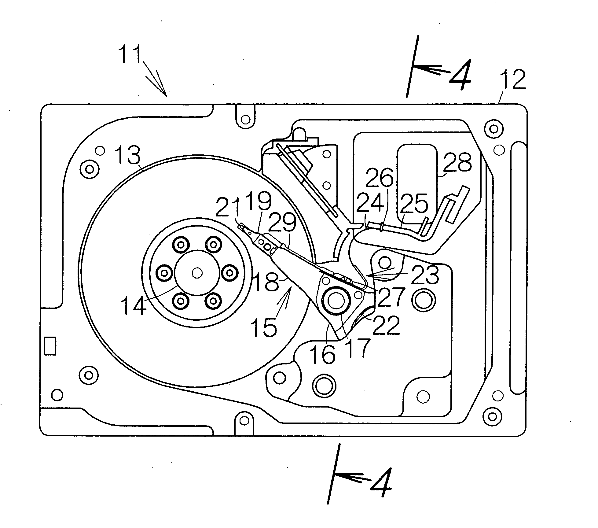
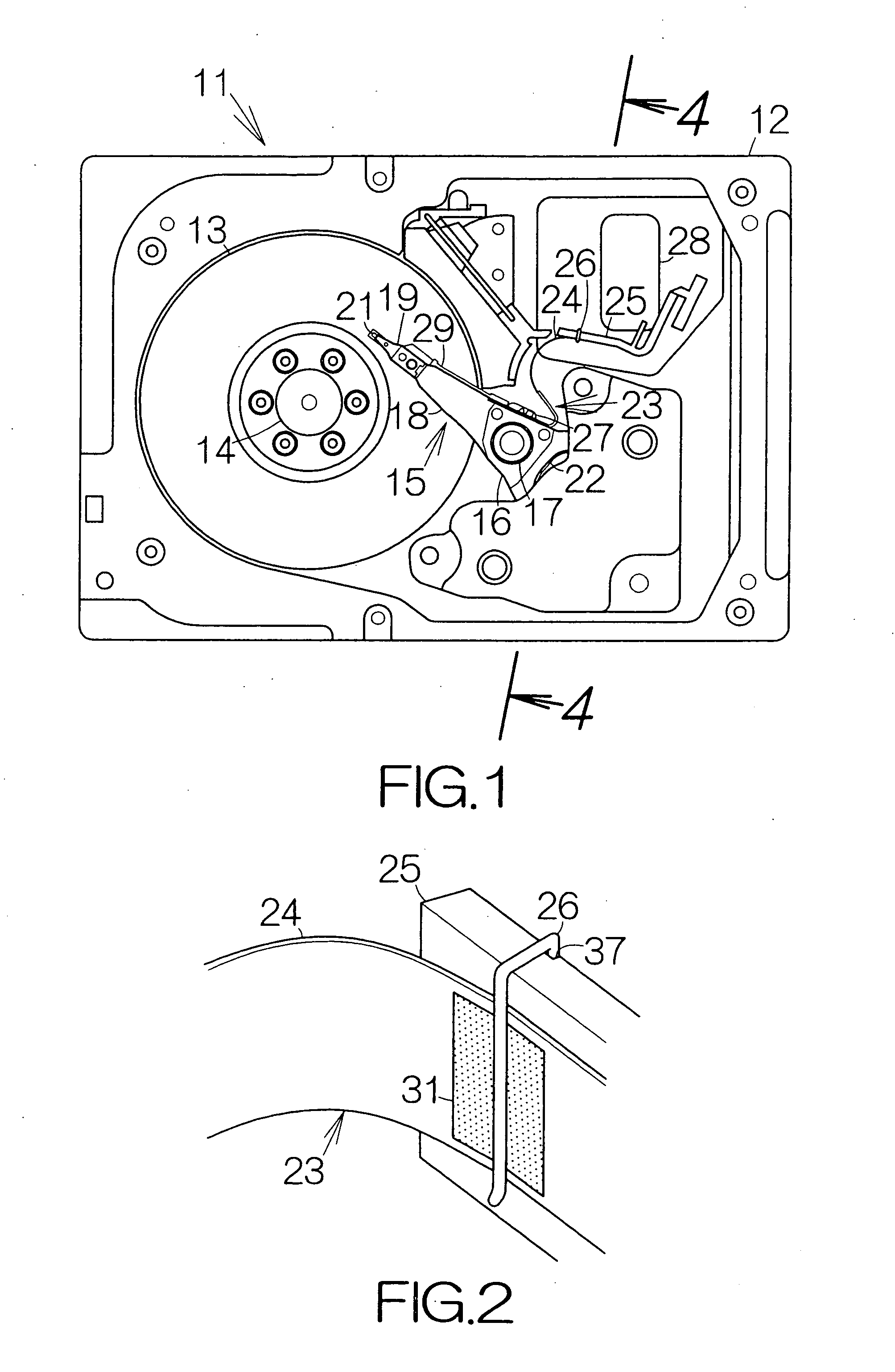
[0031]FIG. 1 schematically illustrates the inner structure of a hard disk drive (HDD) 11 as an example of a recording disk drive or storage device according to an embodiment of the present invention. The HDD 11 includes a box-shaped main enclosure 12 defining an inner space. At least one magnetic recording disk 13 is mounted on the driving shaft of a spindle motor 14 within the main enclosure 12. The spindle motor 14 is allowed to drive the magnetic recording disk 13 for rotation at a higher revolution speed such as 10,000 rpm, 15,000 rpm, or the like, for example. A cover, not shown, is coupled to the main enclosure 12 so as to define the closed inner space between the main enclosure 12 and the cover itself.

[0032] A head actuator 15 is also accommodated in the inner space of the main enclosure 12. The head actuator 15 comprises an actuator block 16. The actuator block 16 is coupled to a vertical support shaft 17 for relative rotation. The rotation of the actuator block 16 allows t...


PUM

PropertyMeasurementUnit
thicknessaaaaaaaaaa
flexibleaaaaaaaaaa
electrically-conductiveaaaaaaaaaa

Abstract

A fixing member is spaced from a head actuator by a predetermined distance. A flexible printed circuit board extends at least from the head actuator to the fixing member. The flexible printed circuit board is superposed on the surface of the fixing member. A viscoelastic layer and a protecting layer are overlaid on the surface of the flexible printed circuit board. A clip clips all the fixing member, the flexible printed circuit board, the viscoelastic layer and the protecting layer together. When a head slider is positioned, the head actuator changes its attitude relative to a recording disk. The inertial force based on the rotation causes the first flexible printed circuit board to vibrate when the actuator block stops rotating. The viscoelastic layer serves to absorb this residual vibration of the first flexible printed circuit board. Vibration of the flexible printed circuit board can be suppressed.

Description

BACKGROUND OF THE INVENTION [0001] 1. Field of the Invention [0002] The present invention relates to a recording disk drive such as a hard disk drive (HDD). In particular, the invention relates to a recording disk drive comprising: a head actuator; a fixing member spaced from the head actuator by a predetermined distance; and a flexible printed circuit board attached to the head actuator so as to extend at least from the head actuator to the fixing member. [0003] 2. Description of the Prior Art [0004] A head actuator is incorporated in a hard disk drive (HDD) so as to change its attitude relative to a magnetic recording disk. The head actuator comprises an actuator block coupled to a vertical support shaft. Actuator arms are defined in the actuator block. A head suspension is fixed to the corresponding actuator arm so as to support a head slider at the tip end thereof. A first flexible printed circuit board is attached to the actuator block so as to supply a sensing current or a wri...

Claims


Application Information

Patent Timeline
Patent Type & Authority Applications(United States)
IPC IPC(8): G11B5/55G11B33/12G11B5/012G11B17/00G11B21/02G11B33/08G11B33/14H05K1/00H05K1/02H05K3/00H05K3/36H05K7/14
CPCH05K1/0269G11B33/122H05K3/0058H05K3/281H05K3/363H05K2201/0133H05K2201/058H05K2201/09063H05K2201/0989H05K2201/099H05K2201/09918H05K2201/10386H05K2201/10409H05K2201/10598H05K2201/2045H05K2203/0191H05K2203/166H05K2203/167G11B5/4846G11B33/08G11B33/121H05K1/0393
Inventor IZUMI, MITSUHIROYOSHIDA, MITSUAKIKANEKO, HISASHIINO, TSUNEYORIKOMURA, YUKIHIROFUJIMOTO, SHINJIFUNABASHI, KEI
Owner FUJITSU LTD
Why Eureka
Try Eureka