Displacement estimation device and method for the same

Active Publication Date: 2007-07-05
PIXART IMAGING INC
View PDF5 Cites 13 Cited by
  • Summary
  • Abstract
  • Description
  • Claims
  • Application Information

AI Technical Summary

Benefits of technology

[0015] In view of the foregoing, it is an object of the present invention to provide a displacement estimation device which is less sensitive to pattern distortion or light shading.
[0016] Another object of the present invention is to provide a displacement estimation method which is less interfered by noises.

Problems solved by technology

However, if the pattern in any of the two images is distorted, such as rotated, shrunk, or enlarged, or if the pattern is shaded from light, it may easily induce errors in the displacement estimation, for that the method only considers the intensities of the pixels, without taking into consideration the relative relationships among the pixels.
The abovementioned method has a drawback in that, because the intensity difference between pixels in an image may be influenced by noises, the choice of the threshold is very critical to the generation of the feature set.
However, it is difficult to choose an optimum threshold, and any inferior choice will negatively impact the estimation of the displacement vector.

Method used


Image

  • Displacement estimation device and method for the same
  • Displacement estimation device and method for the same
  • Displacement estimation device and method for the same

Examples


Embodiment Construction

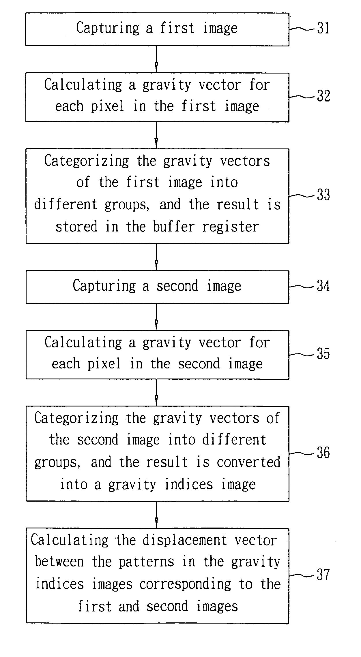
[0038]FIG. 7 shows a displacement estimation device 1 according to a preferred embodiment of the present invention, for use in estimating a displacement vector from a pattern in a first original image to a pattern in a second original image, wherein each original image includes a plurality of pixels. The displacement estimation device 1 includes a vector calculator 11, a vector processor 12, a displacement calculator 13, and a buffer register 14.

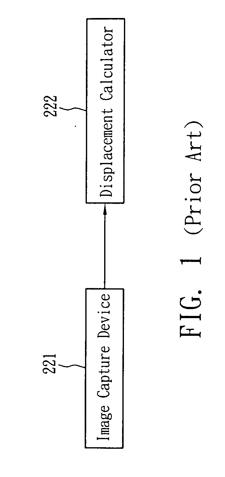
[0039] An image capture device 2 is electrically connected with the vector calculator 11. The image capture device 2 successively captures a first image and a second image, and sends the images to the vector calculator 11. Each of the images includes a plurality of pixels.

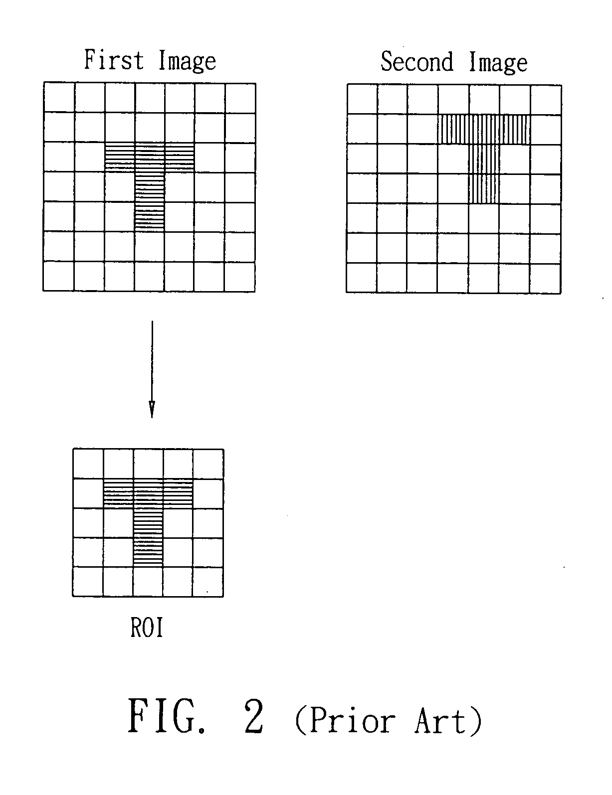
[0040] The vector calculator 11 is electrically connected with the vector processor 12, and it calculates a gravity vector for every pixel in the images. A region of interest (ROI) having a size of N×M pixels is predetermined prior to calculating the gravity vectors by th...


PUM


Abstract

A displacement estimation device includes a vector calculator and a displacement calculator, for use in estimating a displacement vector from a pattern in a first original image to a pattern in a second original image. The vector calculator calculates a parameter for each pixel in the first original image and the second original image. The parameter of a pixel integrates the information of the intensities of all the pixels in a region of interest (ROI) surrounding the pixel, and the relative distances from all the pixels in the ROI to the pixel. The displacement calculator calculates the displacement vector from a pattern in the first original image to a pattern in the second original image based on the parameters calculated by the vector calculator for the first original image and the second original image.

Description

BACKGROUND OF THE INVENTION [0001] 1. Field of the Invention [0002] The present invention relates to a displacement estimation device and a method for the same; in particular, the present invention relates to a device and a method for estimating the displacement between two patterns in two successive images. [0003] 2. Description of the Related Art [0004] Referring to FIG. 1, a conventional optical mouse typically comprises an image capture device 221 and a displacement calculator 222. [0005] The image capture device 221 continuously captures images and transmits the images to the displacement calculator 222. The displacement calculator 222 compares patterns in two successive images and calculates a displacement vector corresponding to the displacement between two corresponding patterns. The displacement vector, as a result of the calculation, is sent to a computer (not shown) by the displacement calculator 222, for moving a cursor on a computer screen. [0006] Referring to FIG. 2, a...

Claims


Application Information

Patent Timeline
IPC IPC(8): G06K9/00G09G5/08
CPCG06F3/0317H04N5/145G06K9/6202G06V10/751
Inventor CHEN, HSIN-CHIALEE, YI-FANGCHAO, TZU-YI
Owner PIXART IMAGING INC
Why Eureka
Try Eureka