Multi-tube solar collector structure

a solar collector and multi-tube technology, applied in solar heat collectors with working fluids, solar heat collectors for particular environments, solar-ray concentration, etc., can solve the disadvantage of loss occasioned by the need for multiple reflections, the collector system of the second group (i

Inactive Publication Date: 2007-07-12
AREVA SOLAR
View PDF23 Cites 29 Cited by
  • Summary
  • Abstract
  • Description
  • Claims
  • Application Information

AI Technical Summary

Benefits of technology

The present invention is a structure that collects solar energy reflected from a field of reflectors. It consists of an inverted trough and a plurality of absorber tubes that are placed inside the trough. These tubes carry a heat exchange fluid. The absorber tubes are positioned side by side in the trough and their diameter is small compared to the size of the trough. The technical effect of this invention is to efficiently collect and utilize solar energy.

Problems solved by technology

The technical problem addressed in this patent text is the inefficiency and complexity of solar collector systems that use a single absorber tube and multiple reflectors. These systems suffer from the need for complex mounting and fluid coupling arrangements, as well as losses caused by multiple reflections. Additionally, the high emissivity-to-absorptance ratio and movement of unconfined heated air from the interior of the reflectors also contribute to the loss of operating efficiency. Finally, these systems are not capable of providing a variable absorption aperture.

Method used


Image

  • Multi-tube solar collector structure
  • Multi-tube solar collector structure
  • Multi-tube solar collector structure

Examples


Embodiment Construction

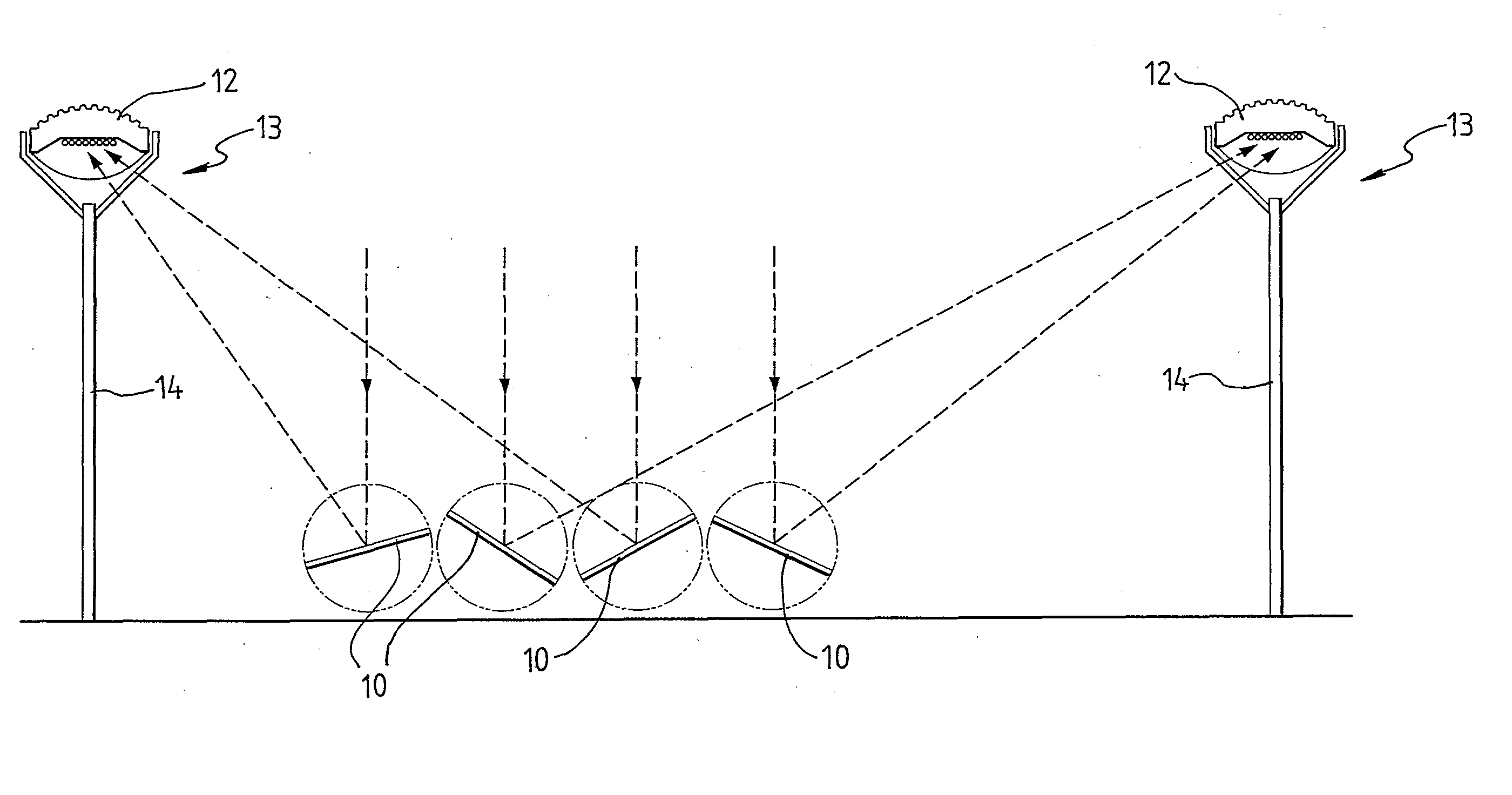
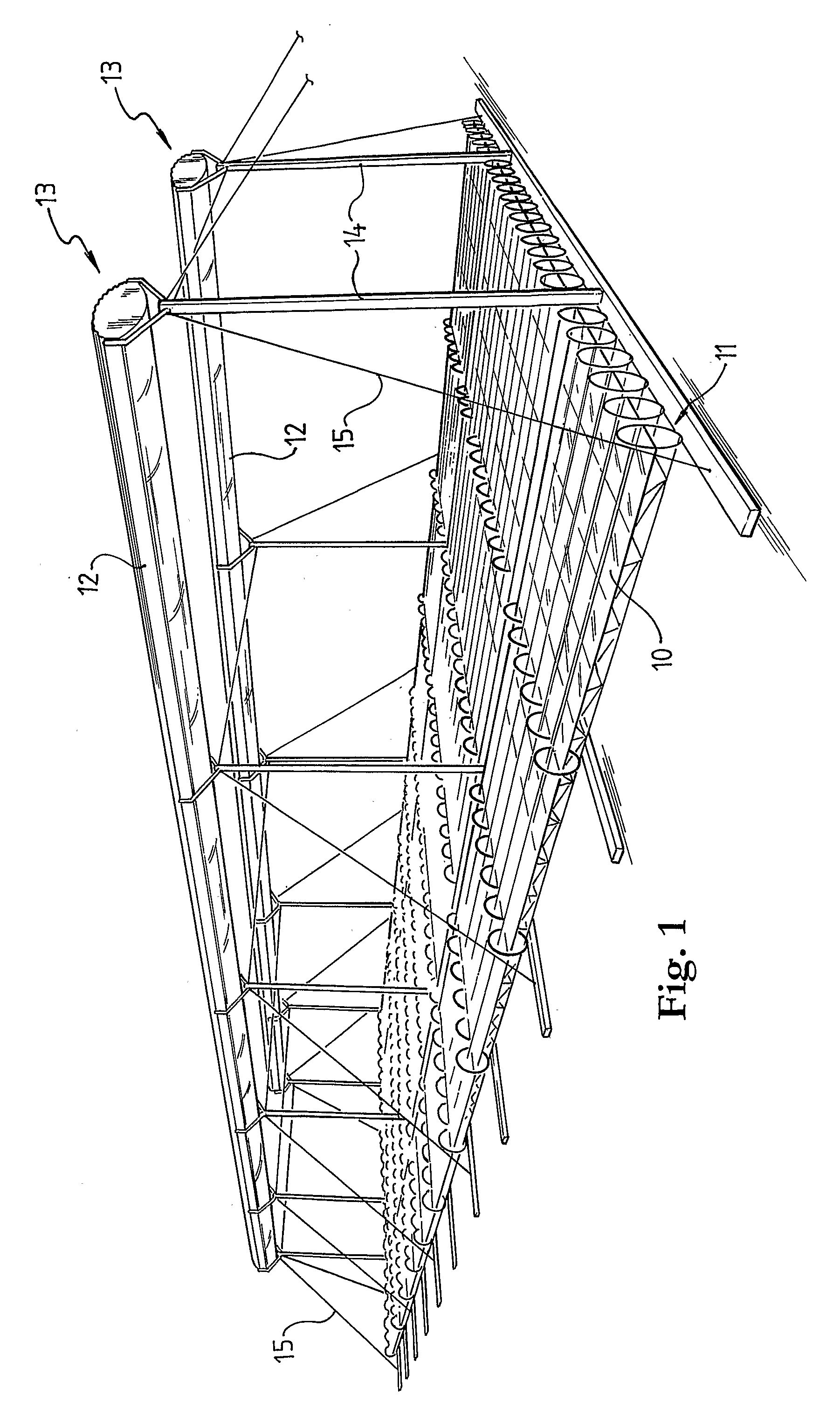
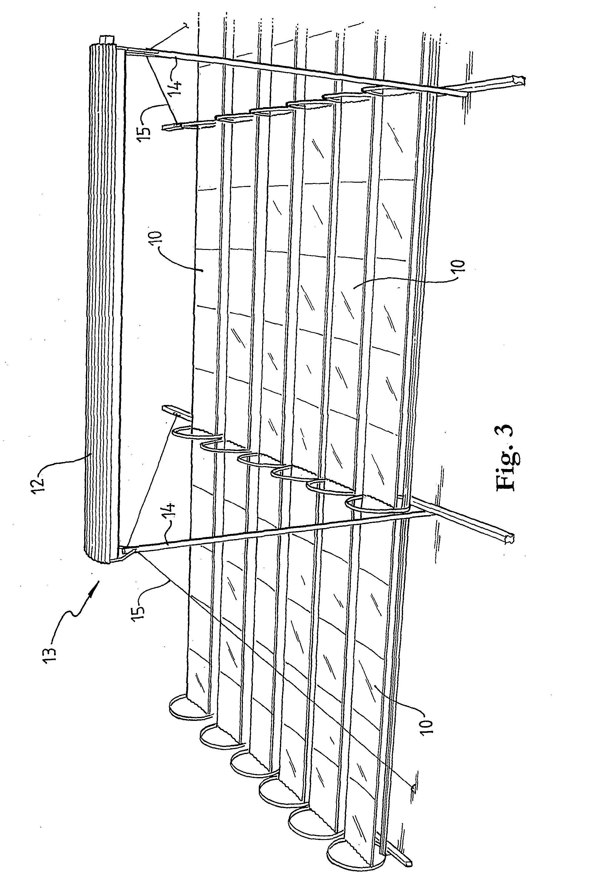
[0024] As shown in FIGS. 1 to 3, the CLFR system comprises a field of ground mounted reflectors 10 that are arrayed in rows 11 and further comprises parallel collector systems 12, each of which is constituted by aligned collector structures 13. A complete CLFR system might occupy a ground area within the range 5×101 m2 to 25×106 m2 and the system as illustrated in FIG. 1 may be considered as a portion only of a larger CLFR system.

[0025] The reflectors 10 may be of the type described in co-pending International Patent Applications numbered PCT / AU2004 / 000883 and PCT / AU2004 / 000884, filed 01 Jul. 2004 by the present Applicant, and the disclosures of these Patent Applications are incorporated herein by reference.

[0026] The reflectors 10 are driven collectively or regionally, as rows or individually, to track movement of the sun (relative to the earth) and they are orientated to reflect incident radiation to respective ones of the collector systems 12, as shown schematically and by way ...


PUM


Abstract

A collector system (12) is disclosed that comprises a row of linearly conjoined collector structures (13). The collector system is arranged to be located at a level above a field of reflectors (10) and to receive solar radiation reflected from the reflectors within the field. The collector structure (13) comprises an inverted trough (16) and, located within the trough, a plurality of longitudinally extending absorber tubes (30) that, in use, are arranged to carry a heat exchange fluid. The absorber tubes (30) are supported side-by-side within the trough and each absorber tube has a diameter that is small relative to the aperture of the trough. The ratio of the diameter of each absorber tube to the trough aperture dimension is of the order of 0.01:1.00 to 0.10:1.00 and, thus, the plurality of absorber tubes functions, in the limit, effectively to simulate a flat plate absorber.

Description


Claims


Application Information

Patent Timeline
Owner AREVA SOLAR
Why Eureka
Try Eureka