
Lock-controlled drawer slide structure

Inactive Publication Date: 2007-07-12
NAN JUEN INT CO LTD
View PDF10 Cites 21 Cited by
  • Summary
  • Abstract
  • Description
  • Claims
  • Application Information

AI Technical Summary

Benefits of technology

[0006] It is a main object of the present invention to provide a structure that utilizes a steel rope to couple the lock device with a latch device. The steel rope can be obtained and mounted easily so the lock device and the latch device can be connected to each other easily without the use of complicated fixing structure.
[0007] It is another object of the present invention to provide a braking device that controls the interlocking device for interlocking and fixing the drawers. As a result, when the braking device is released from being braked by the interlocking device, the braking device retrieves its ability to lock or unlock the upper or lower drawers.
[0008] It is still another object of the present invention to provide a structure having a convenient latch device, wherein the latch device is indirectly fixed on the slide by a fastening plate. As a result, it is very easy to couple and position them.

Problems solved by technology

These drawers are not interlocked securely because the conventional drawer locking structure is not strong enough and an additional connection device must be mounted between the lock head and every drawer.

Method used


Image

  • Lock-controlled drawer slide structure
  • Lock-controlled drawer slide structure
  • Lock-controlled drawer slide structure

Examples


Embodiment Construction

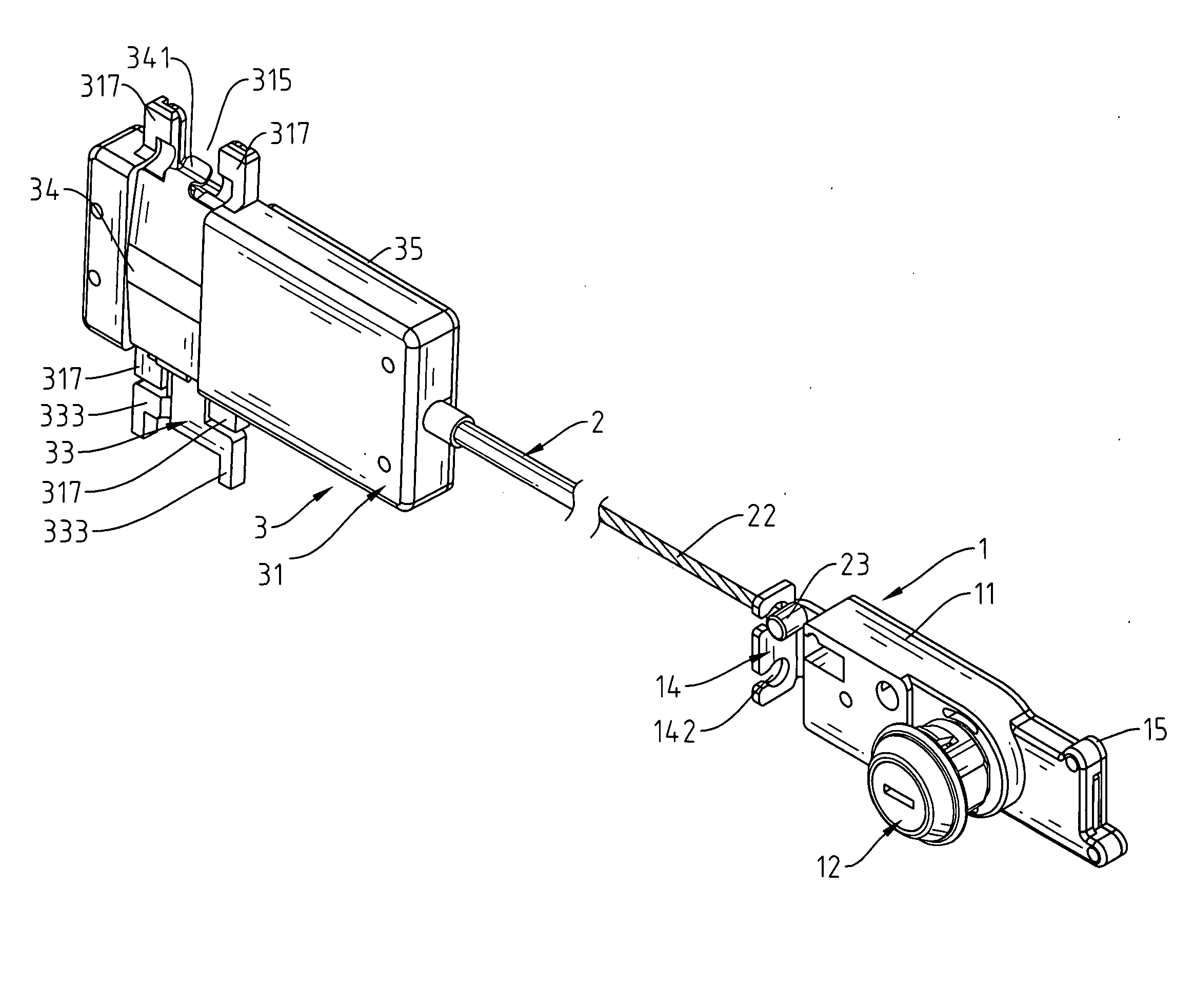
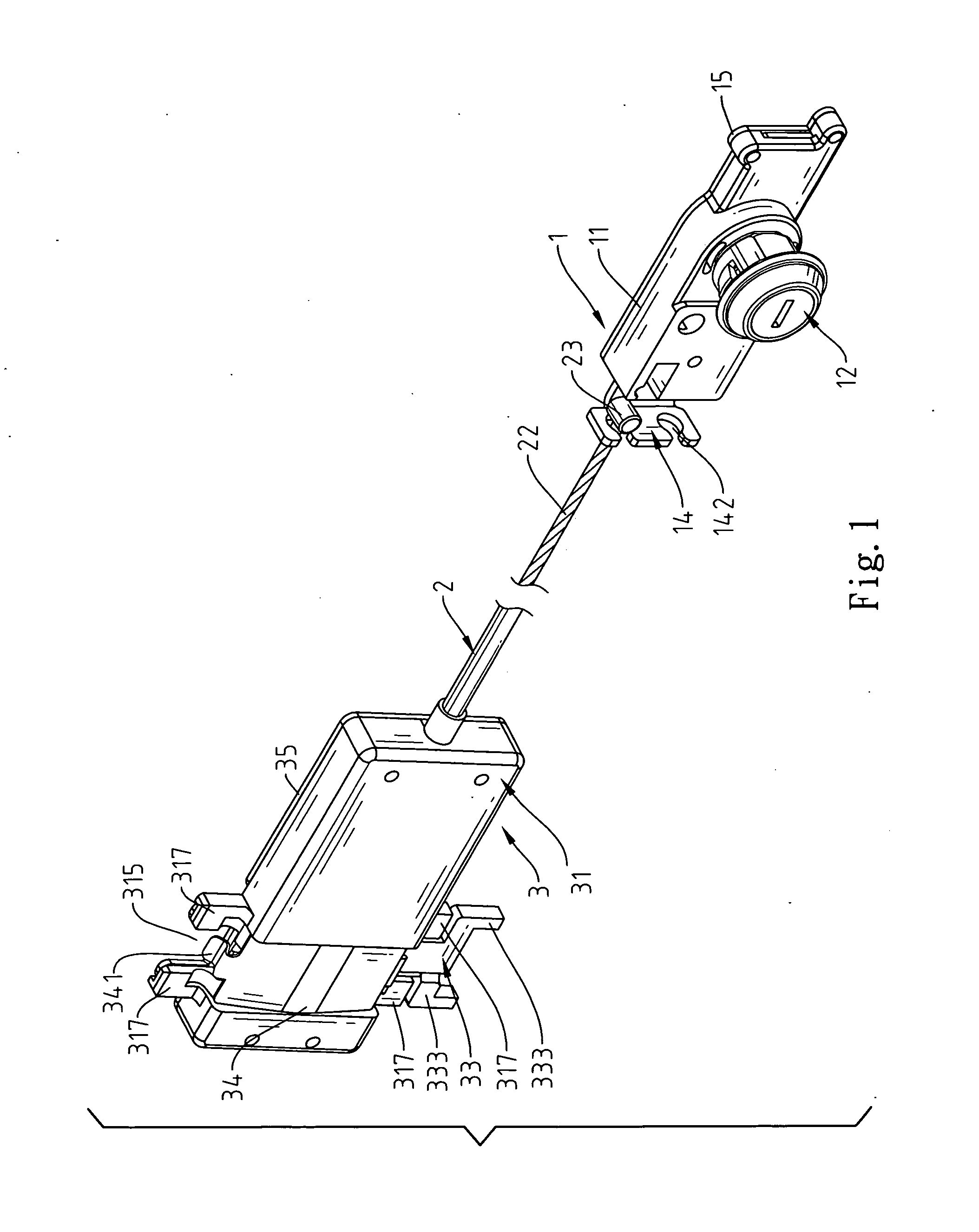
[0018] Referring to FIG. 1, a lock-controlled drawer slide structure of the present invention comprises a lock device 1, a steel rope 2, and a latch device 3, wherein the constituted structure is connected with an interlocking device 4 such that the lock device 1 can lock or unlock the drawers. The steel rope 2 is located between the lock device 1 and the latch device 3, wherein the steel rope 2 can drive the latch device 3 for locking or unlocking the drawers by locking or unlocking the lock device 1.

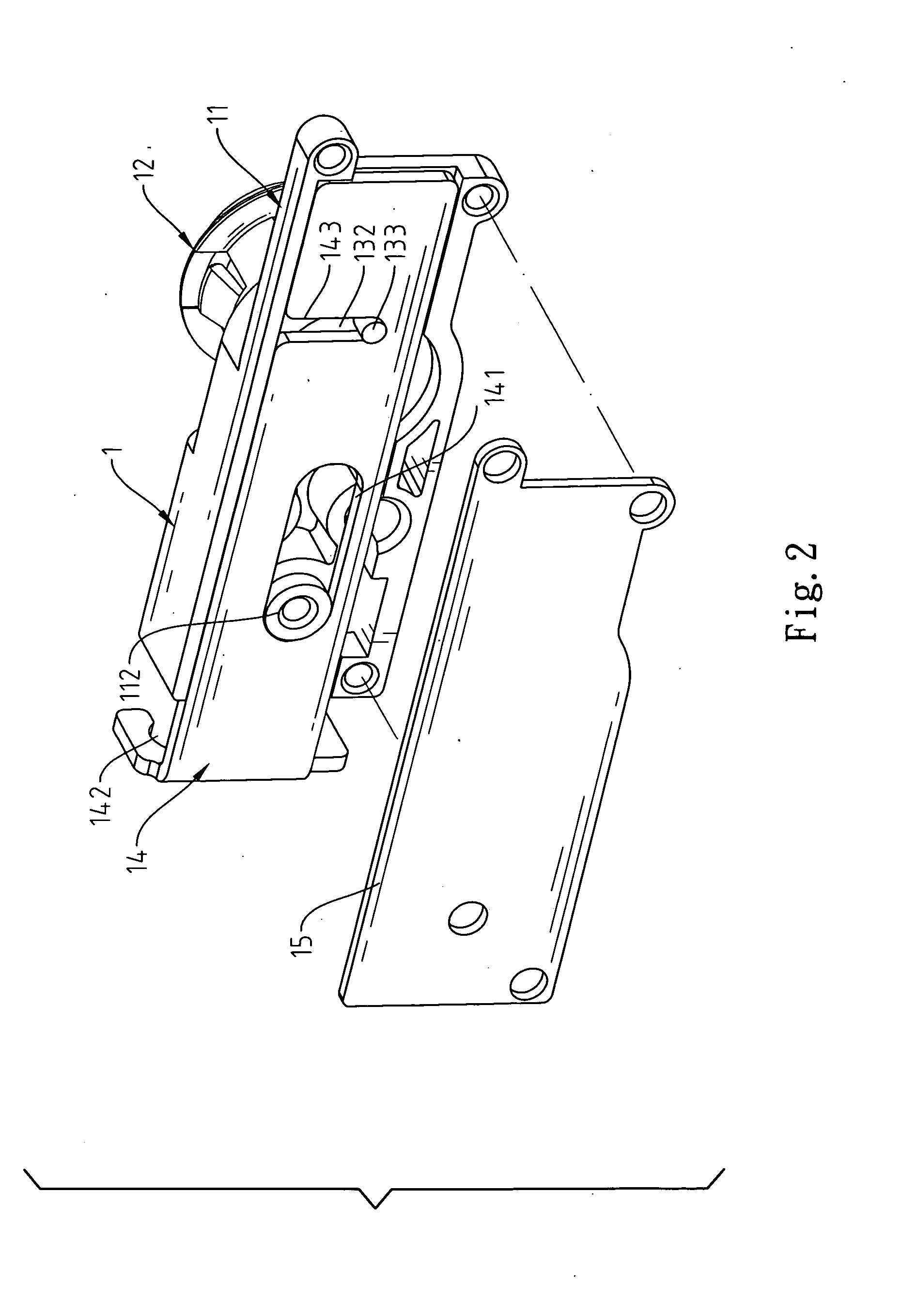
[0019] Referring to FIG. 1 through FIG. 3, the lock device 1 comprises a fixing main body 11, a lock head 12, a rotatory means 13, a pull plate 14, and a fixing plate 15, wherein the lock head 12 is mounted on the outside of the fixing main body 11. An operation trench 111 is formed on the inside of the fixing main body 11 for holding the rotatory means 13, and a guide pillar 112 is mounted near the operation trench 111. A main body 131 of the rotatory means 13 has a diameter dimensio...


PUM


Abstract

A lock-controlled drawer slide structure comprises a lock device, a steel rope, and a latch device, wherein the lock-controlled drawer slide is connected with an interlocking device so as to lock several drawers securely. The lock device comprises a fixing main body, a lock head, a rotatory means, a pull plate, and a fixing plate. The steel rope comprises two fixing heads. The latch device comprises a base, a slidable means, a braking means, a fastening plate, and a cover. The steel rope is utilized to connect the lock device with the latch device securely without the use of complicated fixing structure. The drawers can be locked together by using the braking means that controls the interlocking device. When the braking device is released from being braked by the interlocking device, the braking device retrieves its ability to lock or unlock the upper or lower drawers.

Description

FIELD OF THE INVENTION [0001] The present invention relates to a lock-controlled drawer slide structure, and more particularly to a structure that couples a lock device with an interlocking device for locking the drawers preferably. BACKGROUND OF THE INVENTION [0002] The drawers are commonly applied to the general office facilities such as storage cabinet, data cabinet, and so forth. Besides, the drawer structures are always attached to the desks for storing or collecting data or articles, thereby increasing their practical utility among family or office facilities. [0003] For the existing stacked drawers that can be pulled out individually, if one of the drawers is pulled out, the other drawer that mounts above or underneath this opened drawer may be pulled out simultaneously. Accordingly, a conventional interlocking device that uses a braking rod to lock the upper or lower drawer is mounted among drawers for preventing the other drawers from being pulled out. Besides, a lock head ...

Claims


Application Information

Patent Timeline
IPC IPC(8): E05B53/00
CPCE05B65/462E05B53/003
Inventor HUANG, KUO-SHENG
Owner NAN JUEN INT CO LTD
Features
  • Generate Ideas
  • Intellectual Property
  • Life Sciences
  • Materials
  • Tech Scout
  • Unparalleled Data Quality
  • Higher Quality Content
  • 60% Fewer Hallucinations
Learn More