
Spark plug having excellent capabilities of detecting ion current and suppressing inside sparks

Inactive Publication Date: 2007-07-12
DENSO CORP
View PDF3 Cites 15 Cited by
  • Summary
  • Abstract
  • Description
  • Claims
  • Application Information

AI Technical Summary

Benefits of technology

[0025]It is, therefore, a primary object of the present invention to provide a spark plug for an internal combustion engine which has excellent capabilities of detecting ion current and suppressing inside sparks.
[0035]With the above configuration, it is possible for the spark plug to accurately detect ion current induced therein and reliably prevent occurrence of inside sparks.
[0037]With the above configuration, it is possible to increase flexibility in design of engine layout.
[0039]With the above configuration, it is possible to further enhance the ion current detection capability of the spark plug.
[0041]With the electrically conductive packing, it is possible to secure excellent ion current detection capability of the spark plug even when the electrically conductive coat is formed with low precision.
[0043]With the above configuration, it is possible to further enhance the ion current detection capability of the spark plug.

Problems solved by technology

For example, when knocking occurs in the engine, it affects the waveform of the ion current.
However, when high voltage is applied to the spark plug, corona discharge may occur in a high electric field strength region between an insulator securing the center electrode and a metal shell retaining the insulator.
However, in such long-type spark plugs, a noise having a damped waveform (i.e., the noise waveform 69 in FIG. 6) is found in addition to the above-described spike-like noise.
More specifically, when high voltage is applied to the spark plug to ignite the air / fuel mixture, electric charges accumulate in the space; immediately after the ignition, the electric charges flow to the ground electrode, thereby forming the noise.
Furthermore, the obviousness of the damped waveform noise increases with increase in the axial length of the metal shell, i.e., with increase in the axial length of the threaded portion of the metal shell.
However, when the formation range of the electrically conductive coat on the outer surface of the insulator is improperly chosen, it is easy for “inside sparks” to occur during the ignition.

Method used


Image

  • Spark plug having excellent capabilities of detecting ion current and suppressing inside sparks
  • Spark plug having excellent capabilities of detecting ion current and suppressing inside sparks
  • Spark plug having excellent capabilities of detecting ion current and suppressing inside sparks

Examples


first embodiment

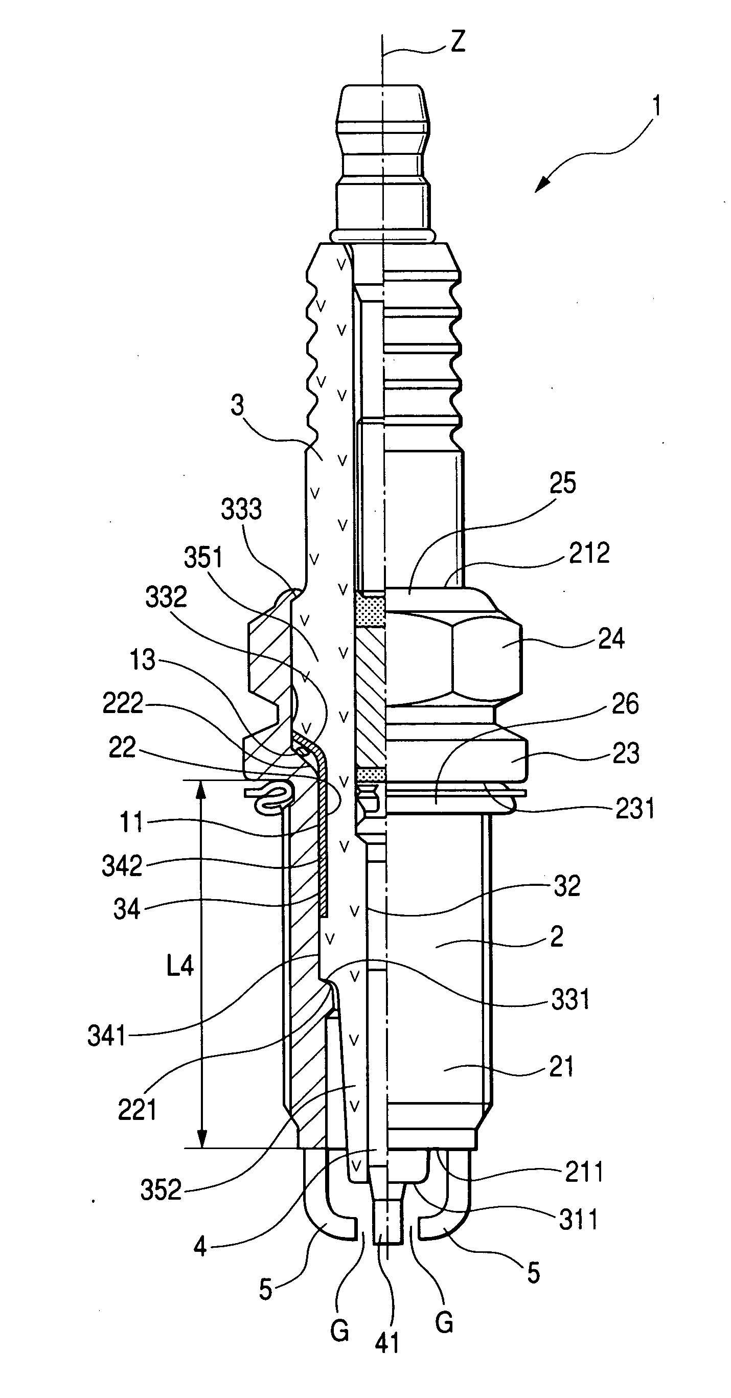
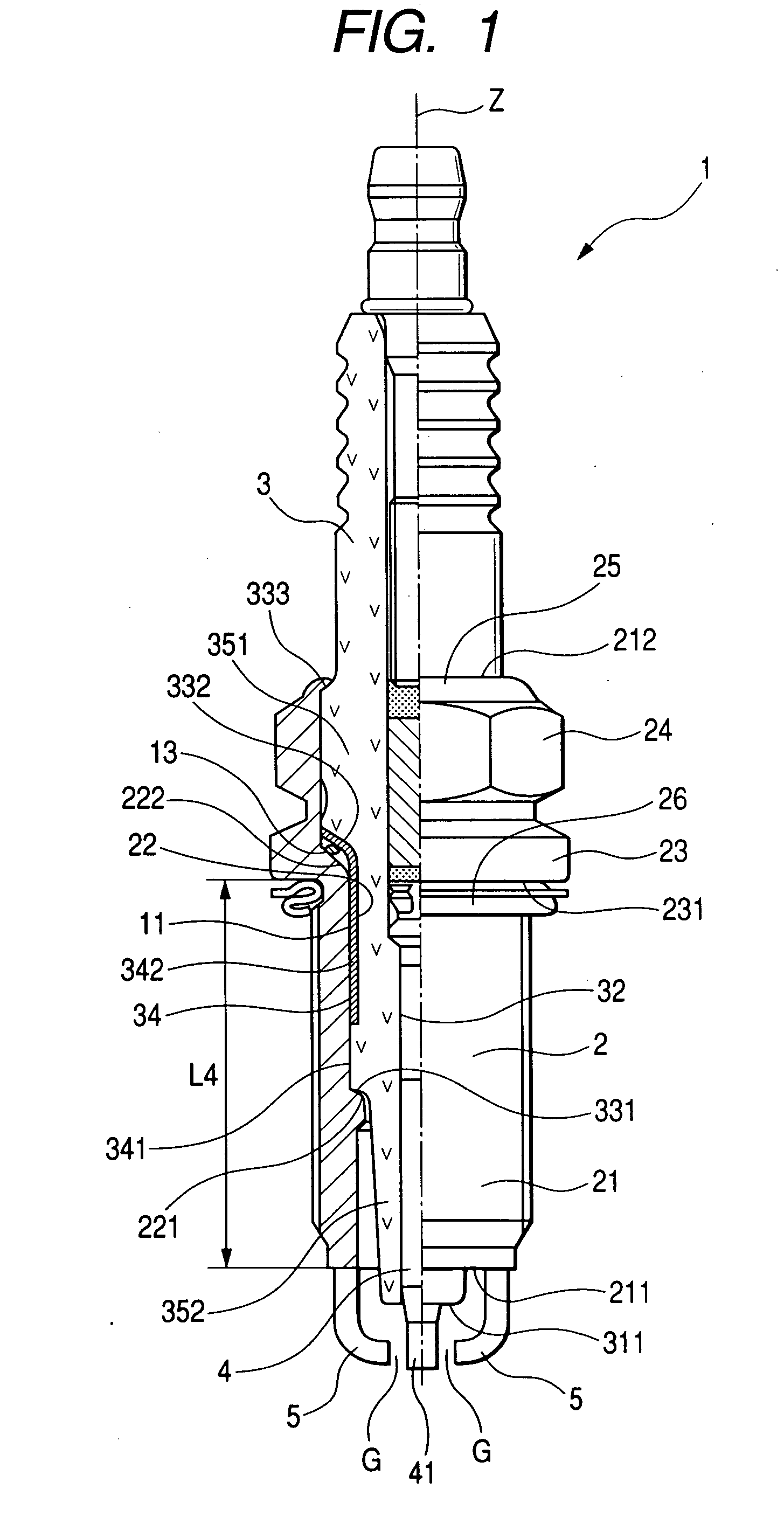
[0060]FIG. 1 shows the overall structure of a spark plug 1 according to the first embodiment of the invention.

[0061]The spark plug 1 is designed for use in an internal combustion engine of a motor vehicle or a cogeneration system. Specifically, the spark plug 1 is designed to perform two different functions in the engine. One function is to ignite the air / fuel mixture within a combustion chamber of the engine; the other is to induce and detect ion current within the combustion chamber of the engine.

[0062]As shown in FIG. 1, the spark plug 1 includes a metal shell 2, an insulator 3, a cylindrical center electrode 4, and a pair of ground electrodes 5.

[0063]The metal shell 2 has a first end 211 and a second 212, which are opposite to each other in an axial direction Z of the spark plug 1.

[0064]It should be noted that in the present embodiment, the axial direction Z of the spark plug 1 coincides with longitudinal directions of the metal shell 2, insulator 3, and center electrode 5.

[0065...

experiment 1

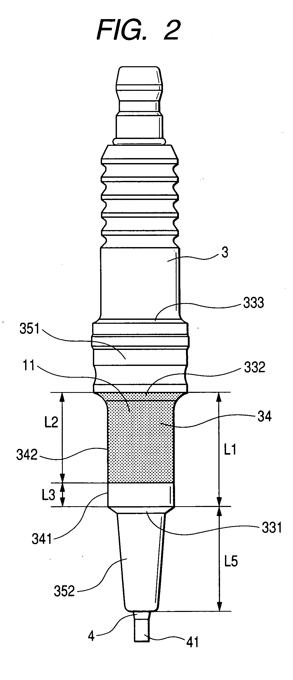
[0114]This experiment was conducted to determine the effect of L1 on the amount of the damped waveform noise that occurs in a spark plug without the electrically conductive coat 11.

[0115]All sample spark plugs tested in the experiment had no electrically conductive coat 11 on the outer surface of the insulator 3.

[0116]Moreover, four different axial lengths L5 of the insulator leg portion 352 were used for the sample spark plugs, i.e., L5=A (high heat range, cold type), L5=A+2 mm, L5=A+4.5 mm, and L5=A+6.5 mm (low heat range, hot type). Hear, A is a constant value in mm.

[0117]Further, for the sample spark plugs of L5=A, two different L1 of 22 mm and 14.5 mm were used; for the sample spark plugs of L5=A+2 mm, two different L1 of 20 mm and 12.5 mm were used.

[0118]Each of the sample spark plugs was tested to measure the amount of the damped waveform noise occurring therein.

[0119]FIG. 7 shows the test results, where the plots of “” indicate the results with the sample spark plugs of L5=...

experiment 2

[0123]This experiment was conducted to determine the effect of L2 on the amount of the damped waveform noise that occurs in a normally-reach type spark plug. Here, the normally-reach type denotes a spark plug type with L4 of 19 mm.

[0124]All sample spark plugs tested in the experiment were of the normally-reach type; L2 was varied for the sample spark plugs.

[0125]Moreover, three different L1 were used for the sample spark plugs, i.e., L1=14.5 mm, L1=12.5 mm, and L1=10 mm.

[0126]Furthermore, in each of the sample spark plugs, the electrically conductive coat 11 is formed only on the second section 342 of the outer surface of the intermediate portion 34 and the surface of the second outer shoulder 332 of the insulator 3.

[0127]Each of the sample spark plugs was tested to measure the amount of the damped waveform noise occurring therein.

[0128]FIG. 8 shows the test results, where the plots of “” indicate the results with the sample spark plugs of L1=14.5 mm, the plots of a“◯” indicate the...


PUM


Abstract

According to the present invention, there is provided a spark plug for an internal combustion engine which includes a tubular metal shell, an insulator, a center electrode, and a ground electrode. In the spark plug, L1, which is the sum of lengths of an intermediate portion and a second outer shoulder of the insulator in the longitudinal direction of the insulator, is greater than or equal to 10 mm; the intermediate portion of the insulator has an outer surface that includes a first and a second section and has an electrically conductive coat only on the second section; and the first section of the outer surface of the intermediate portion of the insulator has a length in the longitudinal direction of the insulator in a range of 1 to 8 mm. With such a configuration,

Description

CROSS-REFERENCE TO RELATED APPLICATION[0001]This application is based on and claims priority from Japanese Patent Application No. 2006-2602, filed on Jan. 10, 2006, the content of which is hereby incorporated by reference into this application.BACKGROUND OF THE INVENTION[0002]1. Technical Field of the Invention[0003]The present invention relates generally to spark plugs for use in internal combustion engines of motor vehicles and cogeneration systems.[0004]More particularly, the invention relates to a spark plug for an internal combustion engine which has excellent capabilities of detecting ion current and suppressing “inside sparks”.[0005]2. Description of the Related Art[0006]There is known a spark plug for an internal combustion engine which is configured to ignite the air / fuel mixture within a combustion chamber of the engine.[0007]To increase the output and improve the fuel economy of the engine, the spark plug is also configured to detect ion current induced therein, thereby d...

Claims


Application Information

Patent Timeline
IPC IPC(8): H01T13/20
CPCH01T13/05Y02E20/14H01T13/41
Inventor ISHINADA, TEIJI
Owner DENSO CORP
Learn More