Method and apparatus for compensating two-dimensional images for illumination non-uniformities

Inactive Publication Date: 2007-07-12
GARCIA CHRISTINE K
View PDF12 Cites 7 Cited by
  • Summary
  • Abstract
  • Description
  • Claims
  • Application Information

AI Technical Summary

Benefits of technology

[0006] Accordingly, it is an advantage of the present invention to provide a digital image scanning system using a two-dimensional scanning element, such as a digital camera.
[0007] It is another advantage of the present invention to provide a two-dimensional digital scanning system in which a digital camera is used to acquire an image, and later digital processing is performed to correct or compensate for non-uniformity in the illumination of the image as it was being scanned.
[0008] It is a further advantage of the present invention to provide a digital scanning system using a two-dimensional scanning device such as a digital camera to acquire a digital image, then analyze portions of the scanned image to find special areas such as border regions, and use the illumination values for these border regions to determine compensation data that can be applied throughout the two-dimensional image and thus compensate for non-uniformities in the illumination of the original image.
[0009] Additional advantages and other novel features of the invention will be set forth in the description that follows and will become apparent to those skilled in the art upon examination of the following or may be learned with the practice of the invention.
[0010] To achieve the foregoing and other advantages, and in accordance with one aspect of the present invention, a method for compensating two-dimensional image data is provided, in which the method comprises receiving an initial image comprising two-dimensional image data and determining a first set of data that comprises a first plurality of pixels at various grid locations within a first region of the two-dimensional image data; analyzing the first set of data for variations in illumination values of the first plurality of pixels, and determining relative non-uniformities of intensity in the first set of data based upon the illumination values; determining a set of initial compensation data used in correcting for the relative non-uniformities of intensity in the first set of data, wherein the set of initial compensation data includes both intensity correction values and corresponding grid location information for at least a portion of the first set of data; and applying the set of initial compensation data to the two-dimensional data, including second portions of the two-dimensional data that are not part of the first set of data using only information based upon the initial image.
[0011] In accordance with another aspect of the present invention, a method for compensating two-dimensional image data is provided, in which the method comprises receiving an initial image comprising two-dimensional image data and determining locations of a first plurality of pixels for a border region of the initial image; determining illumination non-uniformities of the first plurality of pixels based upon variations in image data intensity values of the first plurality of pixels; determining compensation data for a second plurality of pixels, located in a non-border region of the initial image, based upon the illumination non-uniformities of the first plurality of pixels; and applying the compensation data to the second plurality of pixels, to thereby create a third plurality of pixels that are substantially compensated for non-uniformities in illumination of the initial image, using only information based upon the initial image.

Problems solved by technology

However, such a “perfect” set of photosensors may be costly, and in any event they really are not necessary—the scanner is capable of inspecting the acquired pixel values and then “immediately” (i.e., in real time) compensating the variations in those acquired pixel values by adding or subtracting “compensation data” for each of the pixel positions.
On the other hand, if a two-dimensional device, such as a digital camera, is used to acquire image data, then there may not be a “known area” (e.g., some type of two-dimensional area of substantially known, or at least substantially constant, color throughout) available for use in compensating for variations in lighting, or for variations in the sensitivity of the individual photosensors that acquire the pixel data.

Method used


Image

  • Method and apparatus for compensating two-dimensional images for illumination non-uniformities
  • Method and apparatus for compensating two-dimensional images for illumination non-uniformities
  • Method and apparatus for compensating two-dimensional images for illumination non-uniformities

Examples


Embodiment Construction

[0021] Reference will now be made in detail to the one exemplary embodiment of the present invention, an example of which is illustrated in the accompanying drawings, wherein like numerals indicate the same elements throughout the views.

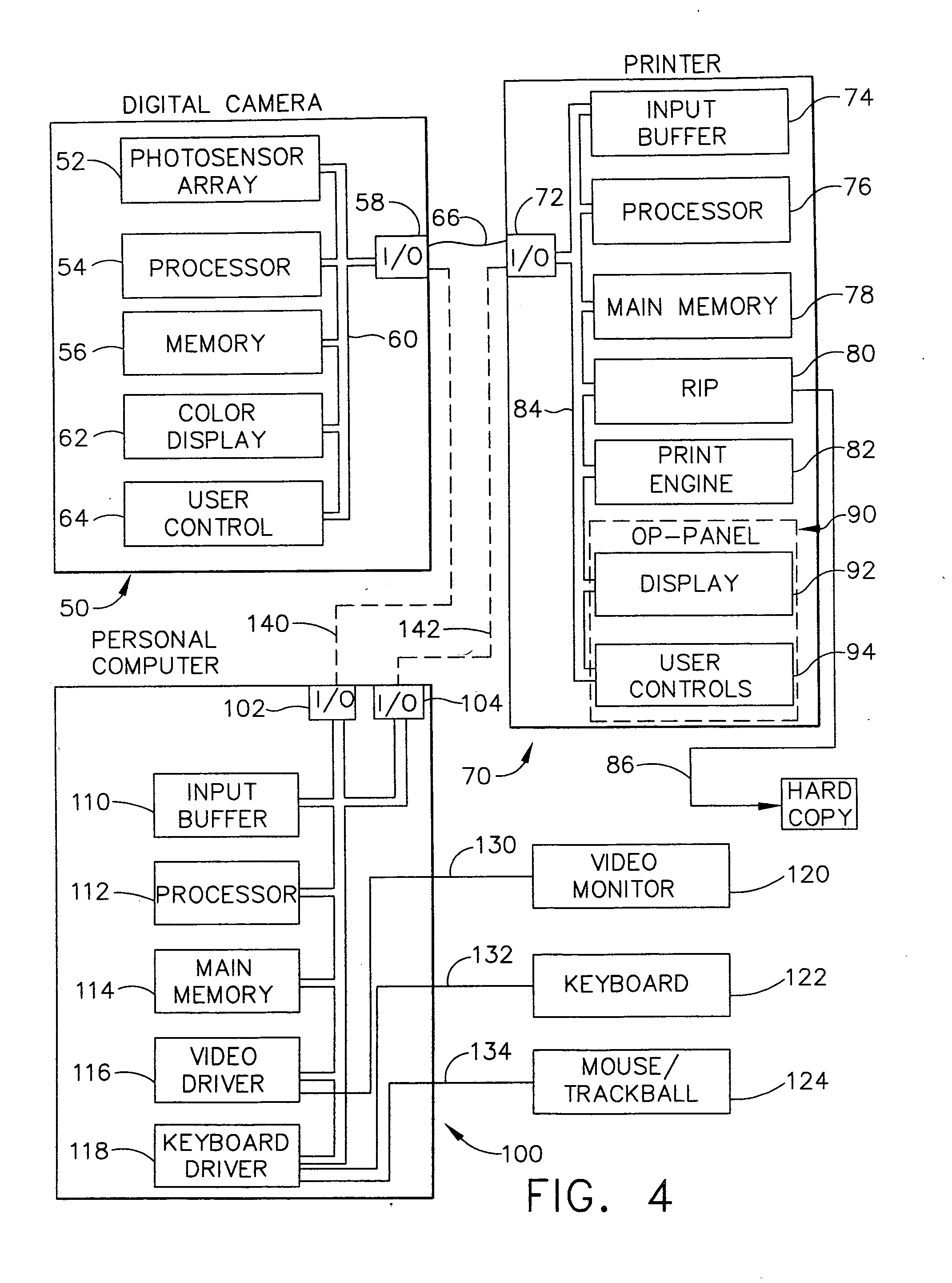
[0022] A digital camera is essentially a scene digitizer, and when used to photograph a document, it can become a document scanner. Using a digital camera as a scanner possesses many advantages over traditional flatbed or sheet fed scanners, including the convenience of upward facing scanning, no requirement for motorized parts in such a scanner, and potentially better scanner performance by use of an array of light-detecting sensors. However, one potential problem in such a scanning system is that the lighting condition may cause variations, or non-uniformity in the illumination, both in the diffuse form and in the specular form. This may occur either when the lighting (or illumination) is provided exclusively by normal ambient light, or by a combi...


PUM


Abstract

A method is provided for compensating two-dimensional images for non-uniformity variations in the illumination of a document, or a scene, that is acquired by a digital camera. The invention can include a printer and / or a personal computer to perform some or all of the compensation calculations, if desired. The present invention captures initial image data, determines a region or area of that data having substantially, or somewhat, uniform pixel intensities and uses that as a background or border region. This border data is used to calculate correction data to correct or compensate the non-border pixel values for non-uniformities in the illumination of the image when it was first acquired, without needing a separate reference frame.

Description

TECHNICAL FIELD [0001] The present invention generally relates to image acquiring equipment and is particularly directed to a two-dimensional imaging device of the type which includes an array of photosensitive elements to acquire multiple pixel values of a two-dimensional image, such as a document. The invention is specifically disclosed as a method for compensating two-dimensional images for non-uniformity variations in the illumination of a document, or a scene, that is acquired by a digital camera. The invention can include a printer and / or a personal computer to perform some or all of the compensation calculations, if desired. BACKGROUND OF THE INVENTION [0002] Image data acquired by photosensors may be in a single dimension, or in two dimensions. Image scanners typically acquire image data in a single dimension (“1-D” data), using a movable scan bar. The scan bar starts at a predetermined “X” position (along the left edge of a document, for example), and the multiple photosens...

Claims


Application Information

Patent Timeline
IPC IPC(8): H04N1/40
CPCH04N1/401H04N5/2354H04N5/217H04N23/81H04N23/74
Inventor CUI, CHENGWU
Owner GARCIA CHRISTINE K
Why Eureka
Try Eureka