Magnet valve

US20070164244A1Inactive Publication Date: 2007-07-19ROBERT BOSCH GMBH

Image

  • Magnet valve
  • Magnet valve
  • Magnet valve

Examples


Embodiment Construction

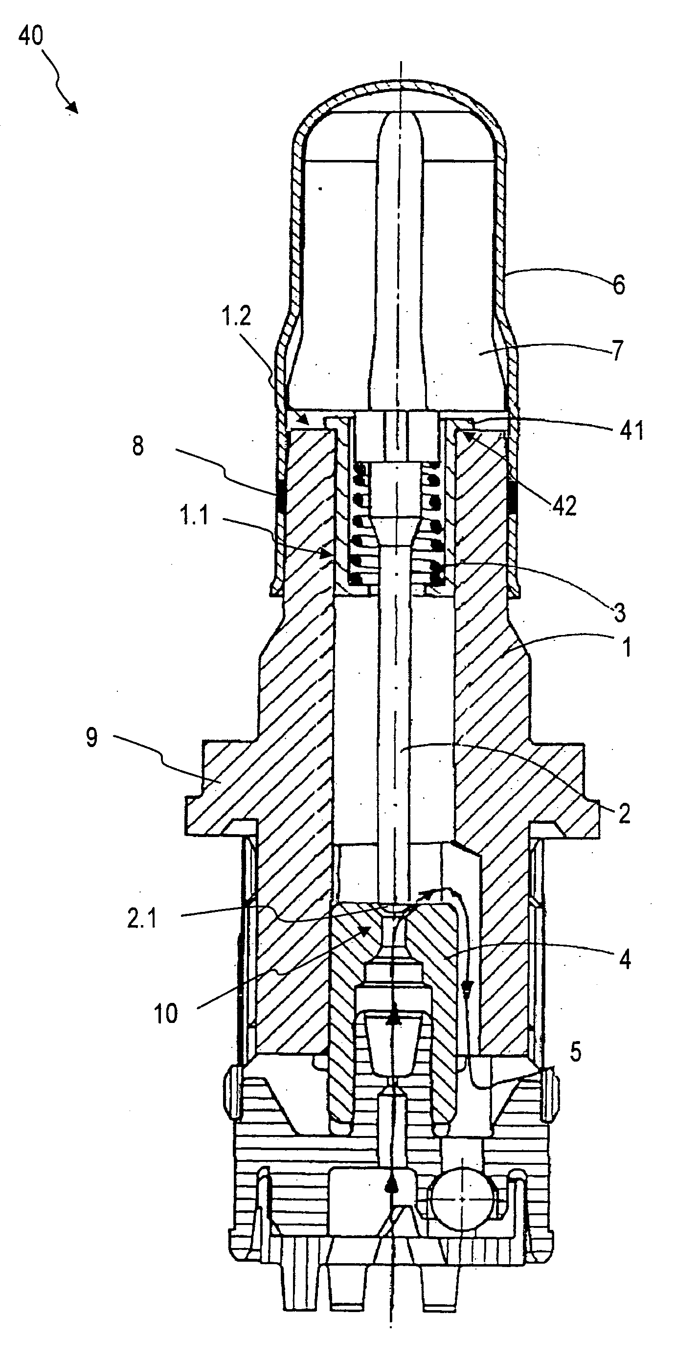
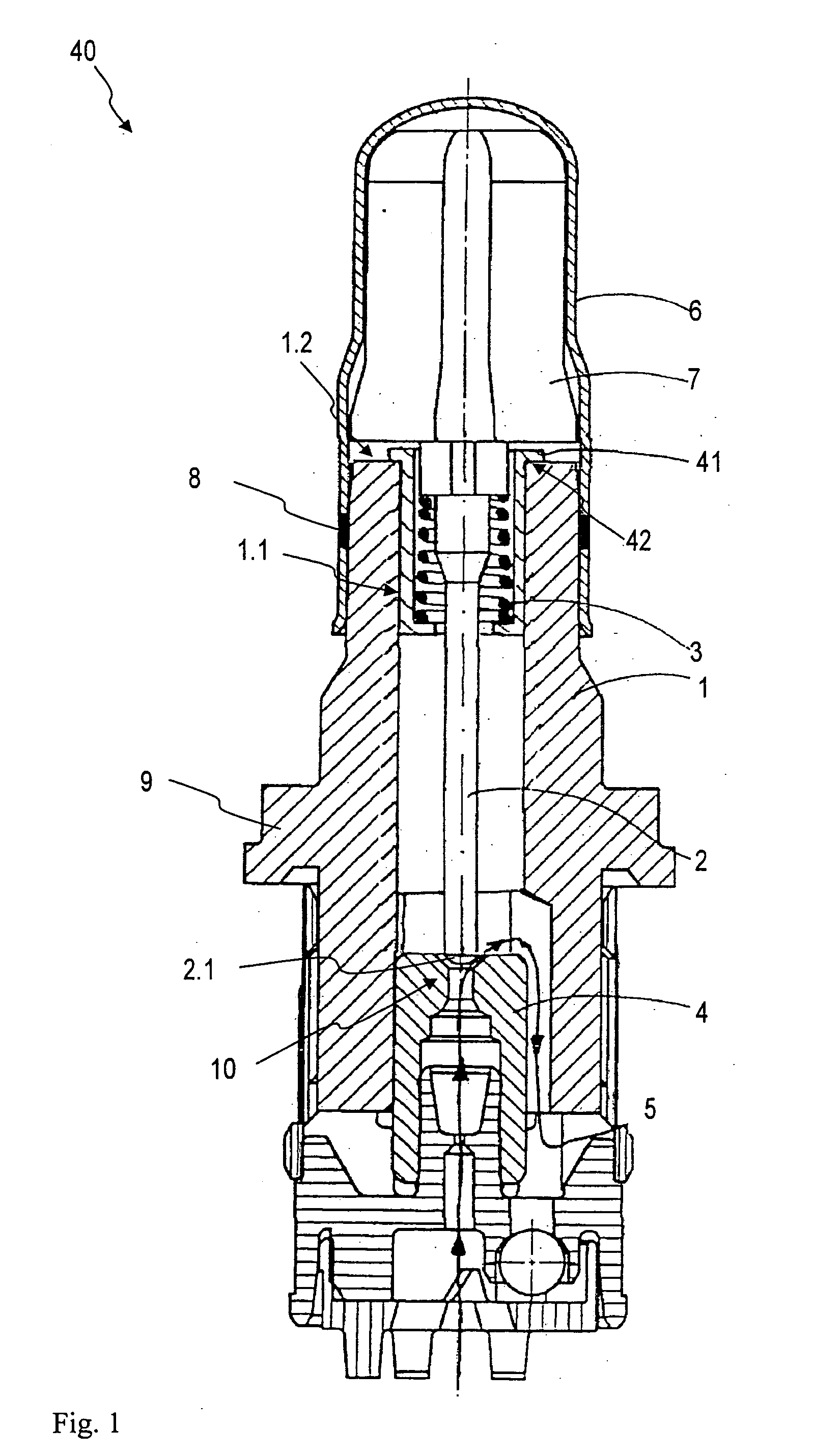
[0013] As can be seen from FIG. 1, one exemplary embodiment of a magnet valve 40 of the invention, analogously to the conventional magnet valve 60 of FIG. 3, includes, besides a magnet unit not shown, a valve cartridge, which includes a capsule 6, a valve insert 1, a tappet 2 with a sealing dome 2. 1, a restoring spring 3, and an armature 7. The capsule 6 and the valve insert 1 of the valve cartridge are joined together by pressing, and by means of a sealing lug 8, the valve cartridge is sealed off hydraulically from the atmosphere. In addition, the valve insert 1 absorbs the pressure forces that occur in the hydraulic system and carries them via a calked flange 9 to a calking region, not shown, on a fluid block. In addition, the valve insert 1 receives the so-called valve body 4, which includes a valve seat 10 into which the sealing dome 2.1 of the tappet 2 plunges in sealing fashion, in order to perform the sealing function of the magnet valve 40. The flow path of the fluid throug...


PUM


Abstract

The invention relates to a magnet valve, having a valve insert and a tappet guided movably in the valve insert, having a sealing dome which plunges in sealing fashion into a sealing seat of a valve body, and the tappet is movable counter to the spring force of a restoring spring. According to the invention, a bracing bush, disposed outside a flow path in a bore of the valve insert, which receives the restoring spring and braces it and radially guides it from outside.

Description

REFERENCE TO FOREIGN PATENT APPLICATION [0001] This application is based on German Patent Application No. 10 2006 002 638.1 filed 19 Jan. 2006, upon which priority is claimed. BACKGROUND OF THE INVENTION [0002] 1. Field of the Invention [0003] The invention is directed to an improved magnet valve of the type used, for example in hydraulic fluid systems. [0004] 2. Description of the Prior Art [0005] A conventional magnet valve, in particular for a hydraulic unit, which is used for instance in an antilock brake system (ABS) or a traction control system (TCS) or an electronic stability program system (ESP system), is shown in FIG. 3. As can be seen from FIG. 3, the conventional magnet valve 60, which is open when without current, includes, besides a magnet unit not shown, a valve cartridge that in turn includes a capsule 6, a valve insert 1, a tappet 20 with a sealing dome 21, a restoring spring 30, and an armature 7. In the production of the magnet valve 60, the capsule 6 and the valv...

Claims


Application Information

Patent Timeline
19 Jul 2007
Publication
US20070164244A1
IPC
F16K31/02
CPC
F16K31/0658; B60T8/363; F16K31/0693
Inventors
KRATZER, DIETMAR