Three-dimensional imaging device
a three-dimensional imaging and imaging device technology, applied in the field of three-dimensional imaging devices, can solve the problems of difficult use of conventional methods for displaying an enlarged stereoscopic image using parallax, and not only can systems provide an enlarged stereoscopic image to doctors, and achieve the effect of improving the accuracy of image display
- Summary
- Abstract
- Description
- Claims
- Application Information
AI Technical Summary
Benefits of technology
Problems solved by technology
Method used
Image


Examples
first embodiment
[0039] First, a configuration of a three-dimensional imaging system of the first embodiment will be described.
[0040] The three-dimensional imaging system of the first embodiment takes an enlarged image of an operating section in brain surgery, for example, to generate image signals that are supplied to a predetermined three-dimensional display device that reproduces a three-dimensional image stereoscopically.
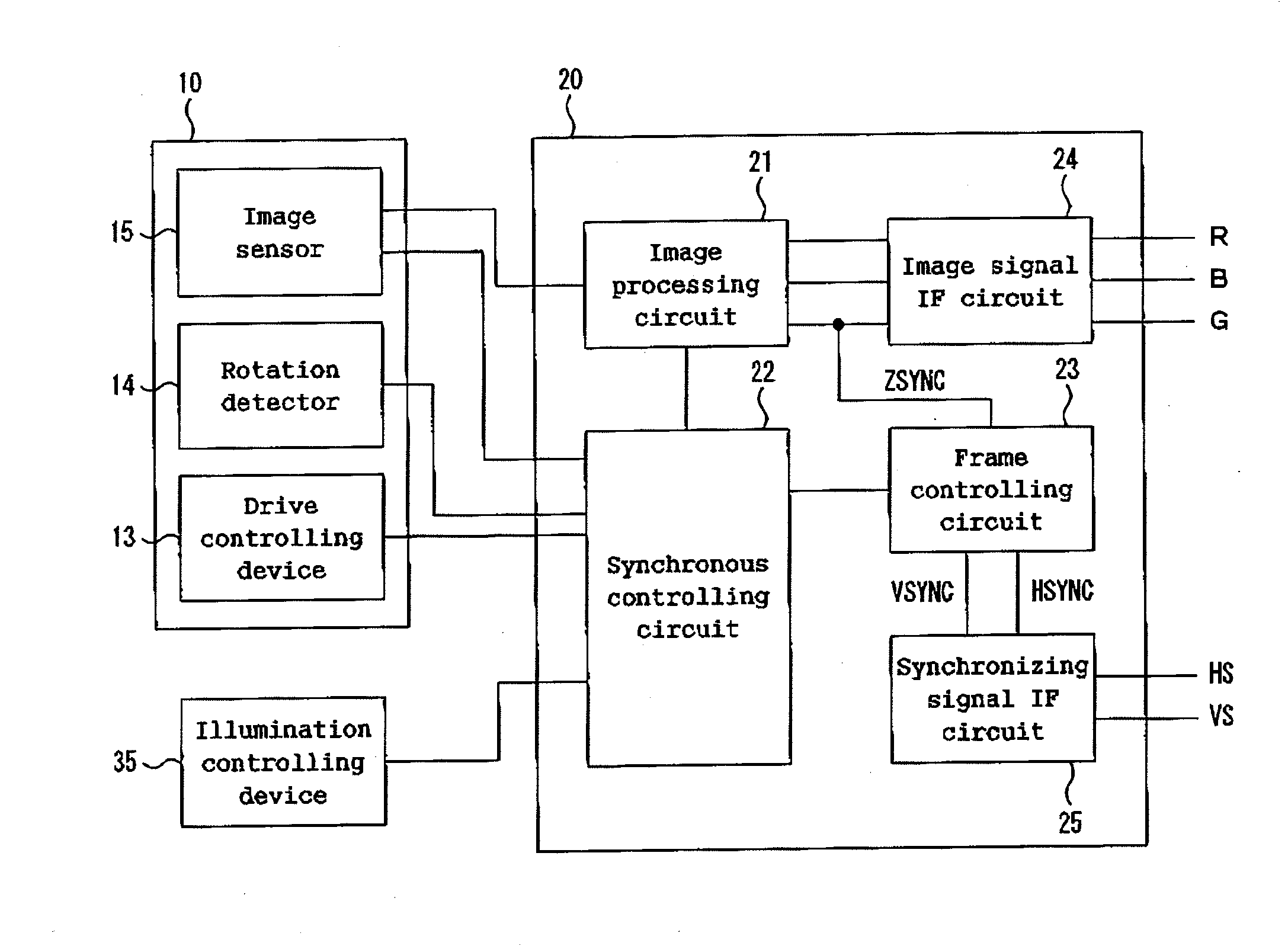
[0041]FIG. 1 is a block diagram of a three-dimensional imaging system concerning the first embodiment.
[0042] As shown in FIG. 1, the three-dimensional imaging system of the first embodiment consists of a camera unit 10, a main unit 20, and illumination unit 30.
[0043] The camera unit 10 takes an image of a subject in afield of view. The main unit 20 processes signals generated by the camera unit 10 to output the above-mentioned image signal. The illumination unit 30 irradiates a subject with illumination light required for the image taking by the camera unit 10.
[0044]FIG. 2 ...
second embodiment
[0077] In the second embodiment, the configuration of the collimating optical system in the illumination unit is different from that in the first embodiment. A reflecting mirror is added at the opposite side of the first anamorphic lens with respect to the linear light source 33. The other configurations are identical to the first embodiment.
[0078]FIG. 5 shows an optical configuration of the collimating optical system 44 of the second embodiment.
[0079] As shown in FIG. 5, the collimating optical system 44 of the second embodiment consists of a reflecting mirror 44a, a first anamorphic lens 44b and a second anamorphic lens 44c.
[0080] The reflecting mirror 44a has an anamorphic reflecting surface whose shape in the section perpendicular to the circumferential direction of the linear light source 33 (i.e., the section parallel to the sheet of FIG. 5) is a parabola. The reflecting mirror 44a is mounted between the flange-shaped screens 32 so that the focus of the parabola is coincide...
third embodiment
[0084] In the third embodiment, the configuration of the collimating optical system in the illumination unit is different from that in the first embodiment. A reflecting mirror is added at the opposite side of the first anamorphic lens with respect to the linear light source 33 in the same manner as the second embodiment. However, in the third embodiment, the shape of the reflecting mirror in the section perpendicular to the circumferential direction is ellipse that is different from a parabola in the second embodiment. The other configurations are identical to the first embodiment.
[0085]FIG. 6 shows an optical configuration of the collimating optical system 54 of the third embodiment. As shown in FIG. 6, the collimating optical system 54 of the third embodiment consists of a reflecting mirror 54a, a first anamorphic lens 54b and a second anamorphic lens 54c. The reflecting mirror 54a has an anamorphic reflecting surface whose shape in the section perpendicular to the circumferenti...
PUM
 Abstract
Description
Claims
Application Information