Method for adjusting the orientation of a camera installed in a vehicle and system for carrying out this method

a technology for adjusting the orientation of a camera and a vehicle, which is applied in the direction of image enhancement, process and machine control, instruments, etc., can solve the problems of not adjusting the camera, the type of system has not been offered for sale to individuals, and the vehicle repairer cannot carry out this adjustmen

a technology for adjusting the orientation of a camera and a vehicle, which is applied in the direction of image enhancement, process and machine control, instruments, etc., can solve the problems of not adjusting the camera, the type of system has not been offered for sale to individuals, and the vehicle repairer cannot carry out this adjustmen

US20070165909A1Inactive Publication Date: 2007-07-19VALEO VISION SA

Image

  • Method for adjusting the orientation of a camera installed in a vehicle and system for carrying out this method
  • Method for adjusting the orientation of a camera installed in a vehicle and system for carrying out this method
  • Method for adjusting the orientation of a camera installed in a vehicle and system for carrying out this method

Examples


Embodiment Construction

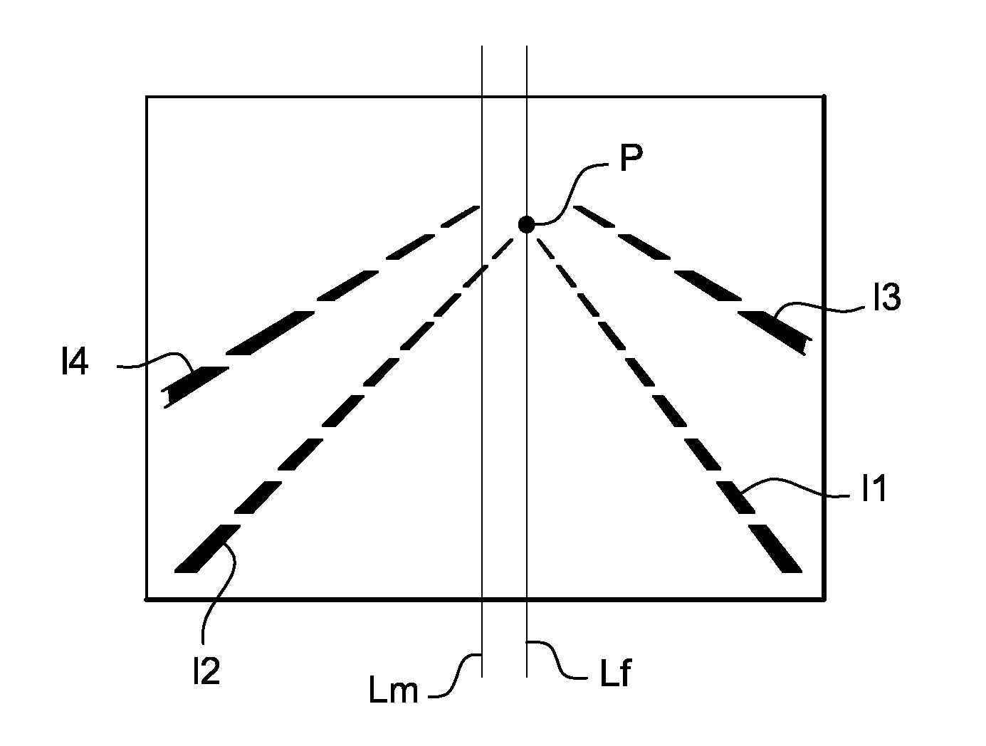
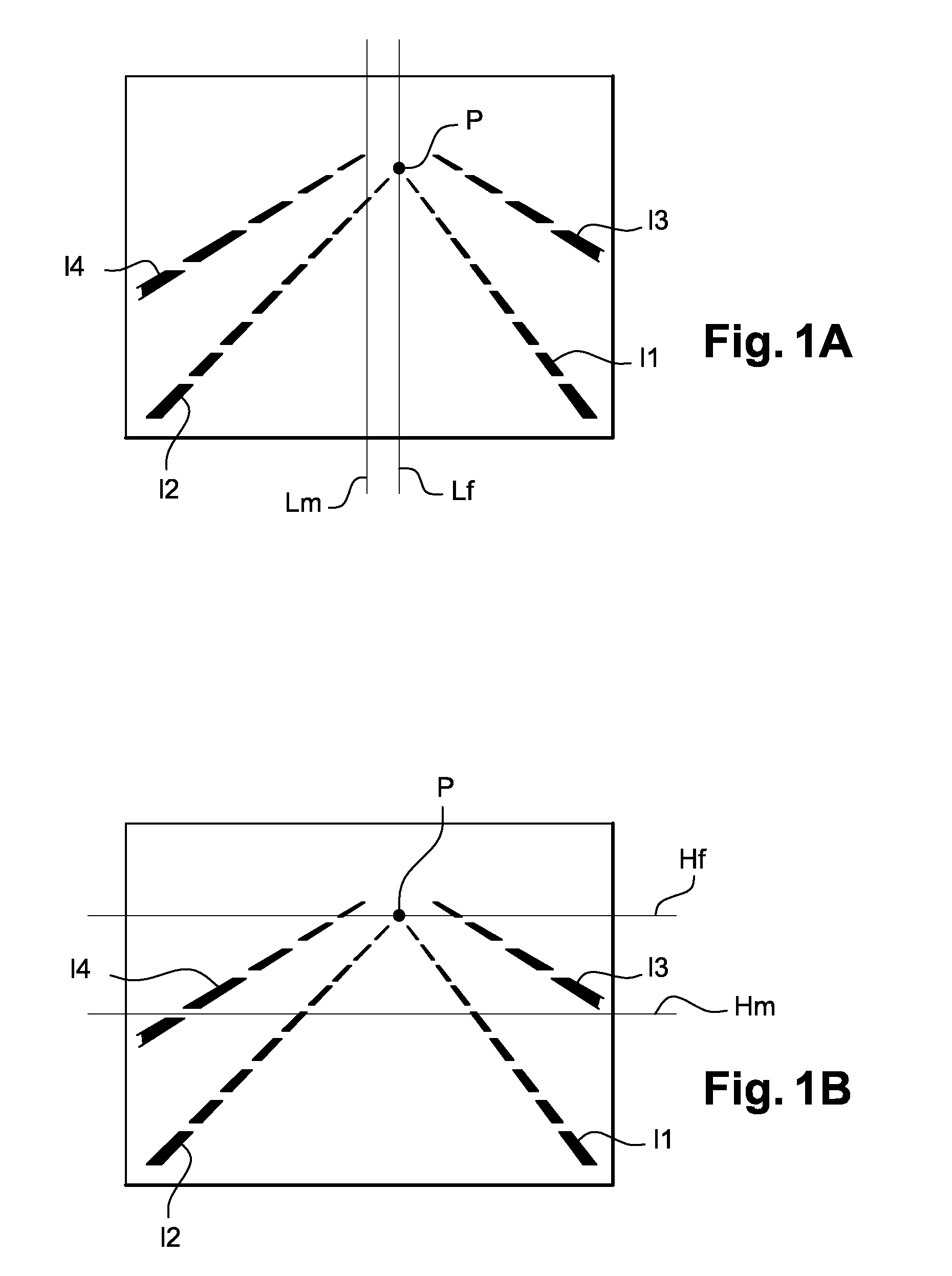
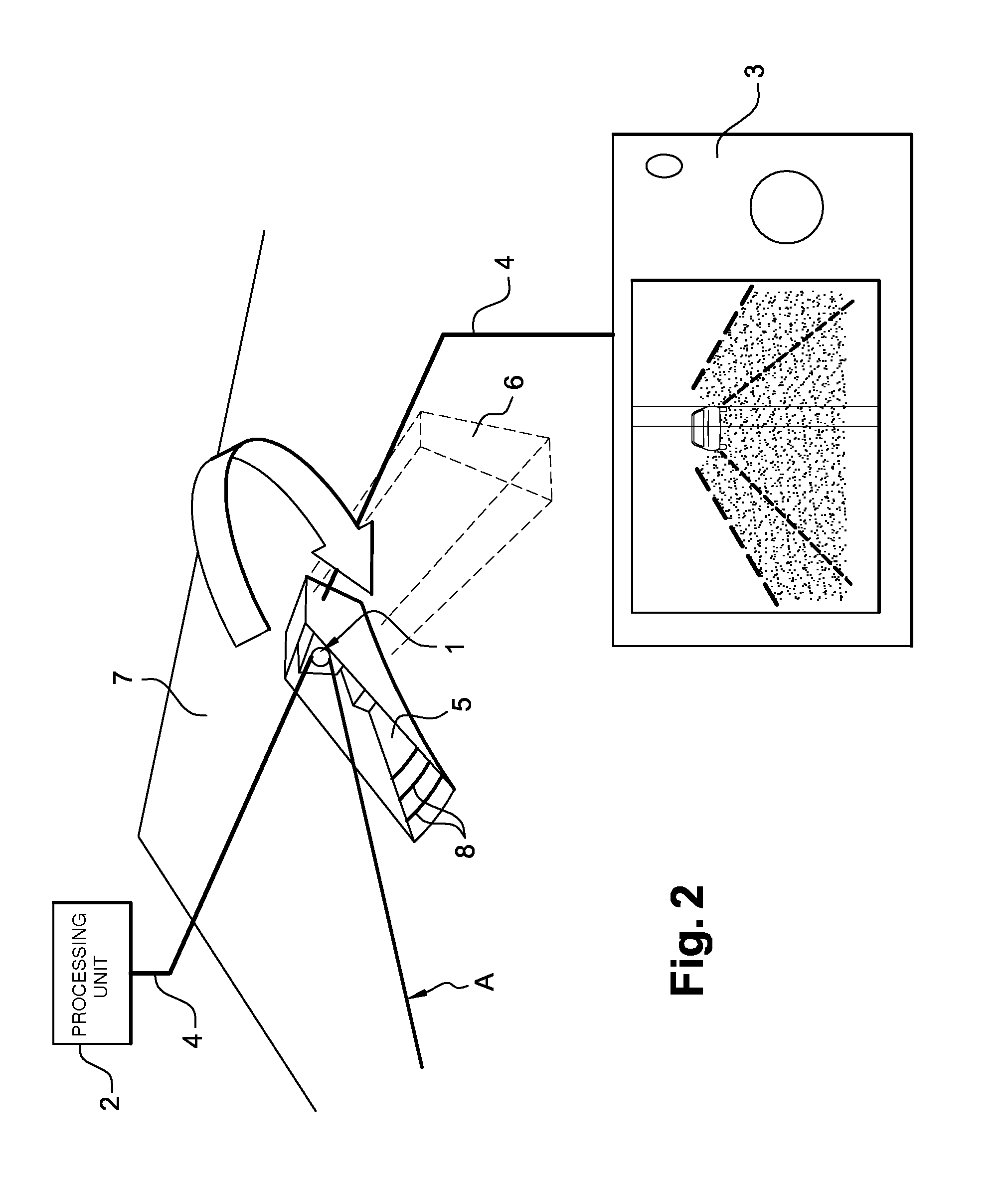
[0046] The invention proposes a method for adjusting the orientation of a camera on board a vehicle in order optimally to carry out a method using this camera. A method using a camera of this type may be, for example, an obstacle detection method. It may also be a method for detecting parallel markings on the ground. The invention will be described specifically for this application for the detection of markings on the ground, referred to hereinafter as white lines. These white lines may be continuous or discontinuous lines or emergency stopping strips.

[0047] The method of the invention is based on the estimation of a vanishing point based on the image of these white lines and on the estimation of a middle in a vertical plane of the image, wherein the middle of the image and the vanishing point have to be superimposed in order for the horizontal orientation of the camera to be optimal. The vertical orientation is produced by matching the vanishing point and the positioning point.

[0...


PUM


Abstract

A method for adjusting an orientation of a camera installed on a vehicle, comprising the following operations: installing the vehicle at a location provided with markings on the ground, detecting these markings, estimating a vanishing point based on these markings, and matching the vanishing point with a positioning point by angular displacement of the camera.

Description

BACKGROUND OF THE INVENTION [0001] 1. Field of the Invention [0002] The invention relates to a system and method for the adjusting, by a user, of the orientation of a camera installed in a vehicle. The user is an individual with little experience in the adjusting of cameras, for example the driver of the vehicle in which the camera to be adjusted is installed. The method of the invention is intended to allow the installation in a vehicle, by an individual, of a system for detecting obstacles or for monitoring white lines. [0003] The invention also relates to a system for carrying out this method. [0004] 2. Description of the Related Art [0005] The invention is used in the field of motor vehicles and, in particular, in the field of vehicle after-sales service for installing systems using a camera in a vehicle. [0006] In the field of motor vehicles, numerous systems are installed on the vehicles for increasing the safety of persons on board the vehicle by facilitating driving of the v...

Claims


Application Information

Patent Timeline
19 Jul 2007
Publication
US20070165909A1
IPC
G06K9/00; G06V10/147
CPC
G05D1/0244; G05D1/0246; G05D2201/0213; G06T2207/30256; G06K9/209; G06T7/0018; G06K9/00798; G06T7/80
Inventors
LELEVE, JOEL; REBUT, JULIEN