Supercharge Your Innovation With Domain-Expert AI Agents!

Screw with ridges and grooves between threads on shank

a technology of ridges and grooves, applied in the field of screws, can solve the problems of increasing the operation time, requiring a lot of physical effort, and users having to apply a huge force to push and rotate the screws

Inactive Publication Date: 2007-07-19
HUMBOLDT STATE UNIVERSITY
View PDF13 Cites 20 Cited by
  • Summary
  • Abstract
  • Description
  • Claims
  • Application Information

AI Technical Summary

Benefits of technology

The present invention is about a screw with a head and a shank connected to the head. The shank has spiral threads and a tip end. The shank has two sections: a first section with cutting ridges and a second section with grooves. The technical effect of this invention is to provide a screw with improved cutting performance and better resistance to wear and corrosion.

Problems solved by technology

However, it is experienced that if the object is a hard object then the users have to apply a huge force to push and rotate the screw.
This not only requires a lot of physical efforts and also increases the operation time.
The debris of the object cannot be removed within the small space and the object could be broken by the accumulated debris.

Method used


Image

  • Screw with ridges and grooves between threads on shank
  • Screw with ridges and grooves between threads on shank
  • Screw with ridges and grooves between threads on shank

Examples


Embodiment Construction

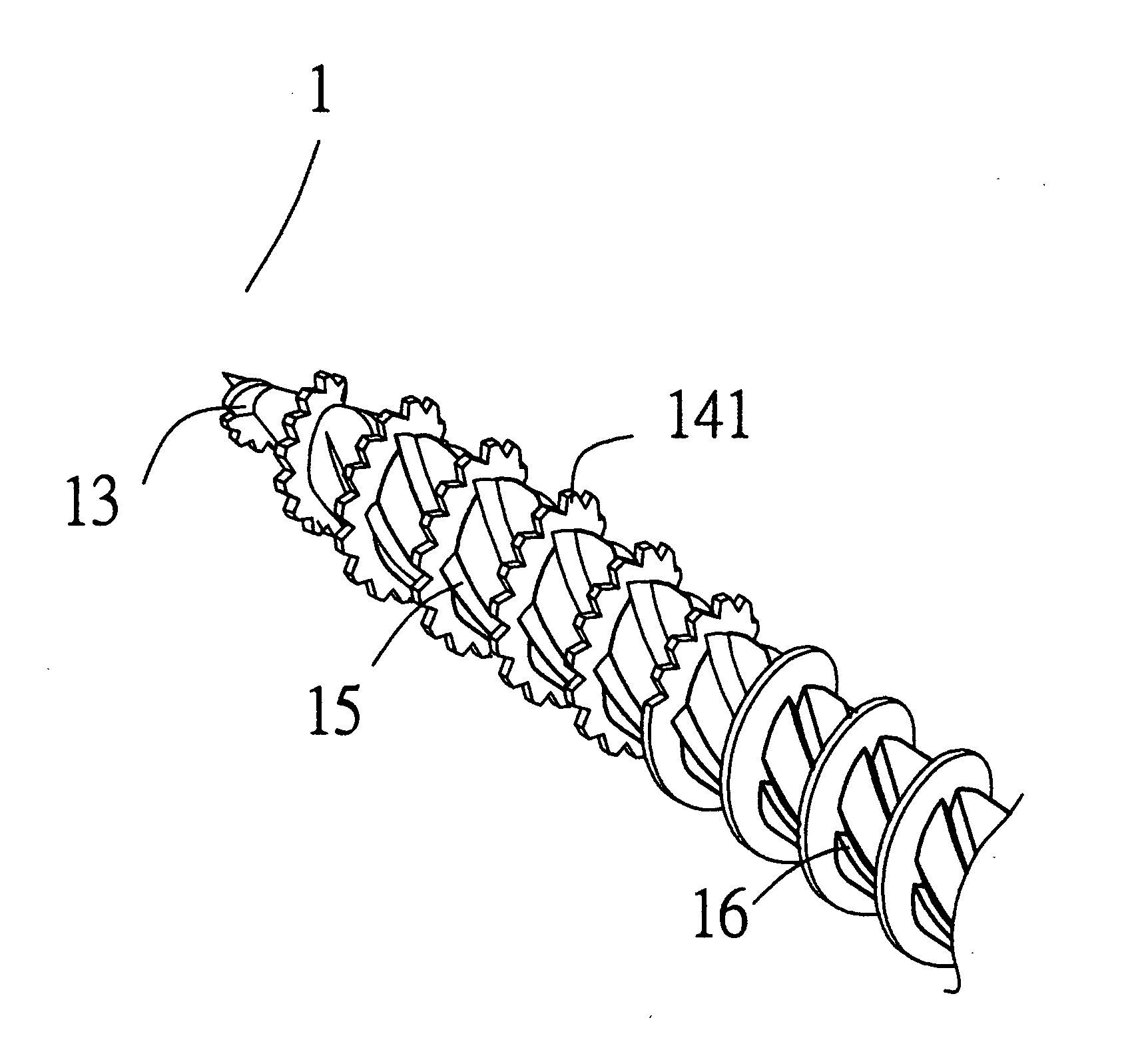
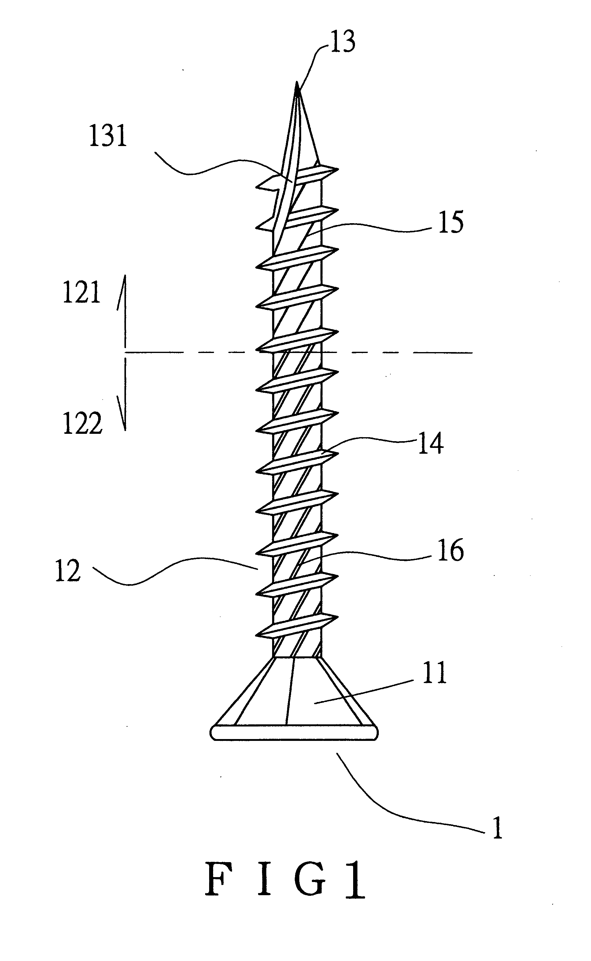
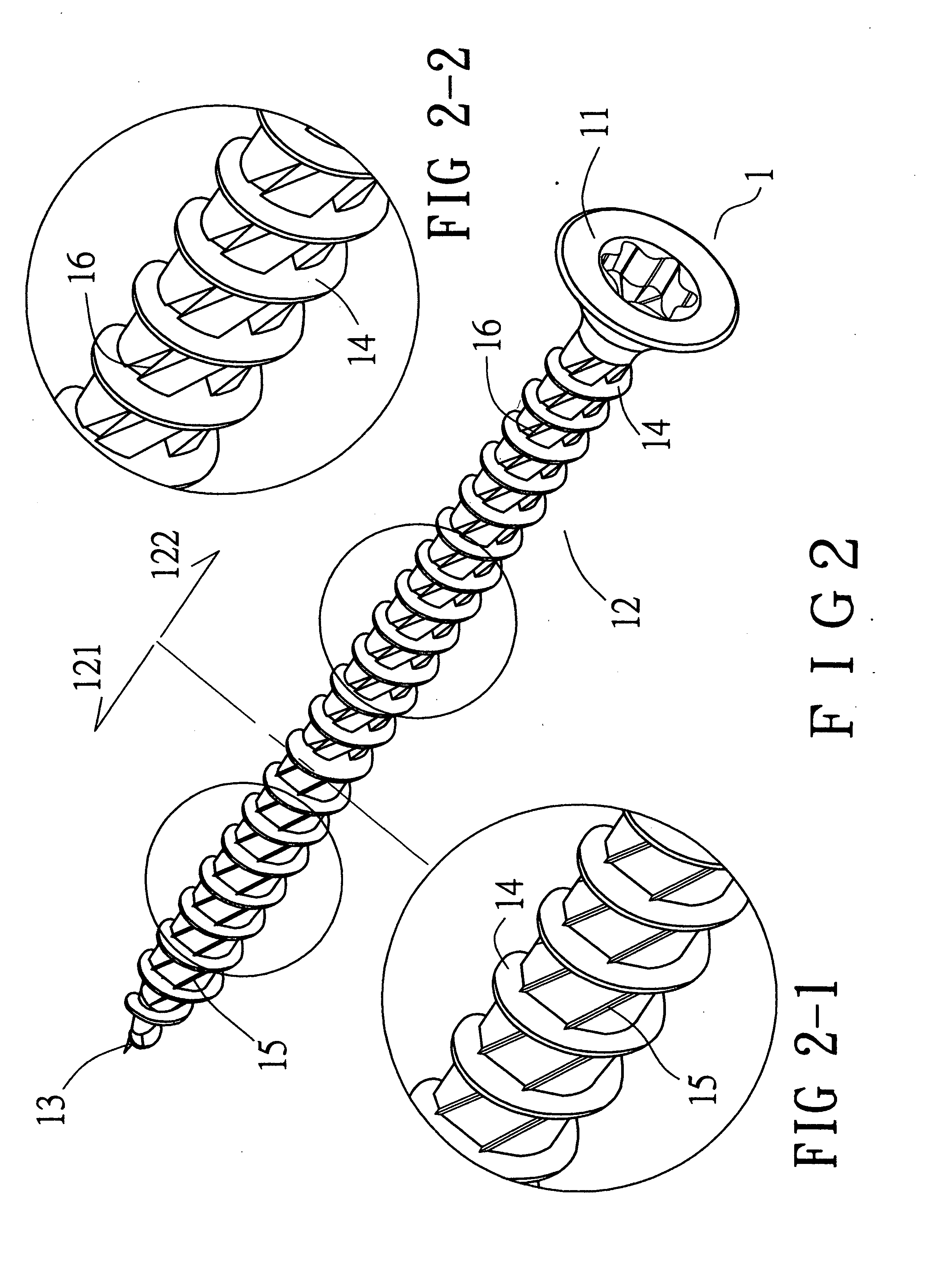
[0014] Referring to FIGS. 1, 2, 2-1, 2-2 and 3, the screw 1 of the present invention comprises a head 11 and a shank 12 is connected to the head 11. A tip end 13 is defined in an end of the shank 12 and located opposite to the head 11. Spiral threads 14 are defined in an outer periphery of the shank 12. At least one cutting groove 131 is defined in an outer periphery of the tip end 13.

[0015] The shank 12 includes a first section 121 including the tip end 13 and a second section 122 which includes the head 11. The first section 121 includes a plurality of cutting ridges 15 extending from the outer periphery of the first section 121 of the shank 12. The cutting ridges 15 are located between the spiral threads 14 and are tilt relative to an axis of the shank 12. The cutting ridges 15 each are an inverted V-shaped ridge which includes a cutting edge. The second section 122 includes a plurality of grooves 16 defined in the shank 12 and the grooves 16 are located between the spiral threa...


PUM

PropertyMeasurementUnit
forceaaaaaaaaaa
structureaaaaaaaaaa

Abstract

A screw includes a head and a shank which includes a tip end. Spiral threads are defined in an outer periphery of the shank which includes a first section including the tip end and a second section including the head. A plurality of cutting ridges extend from the outer periphery of the first section of the shank so as to cut the fibers of the object and remove the debris of the object upward. The second section includes a plurality of grooves defined in the shank so as to receive the debris to prevent the debris from breaking the object.

Description

FIELD OF THE INVENTION [0001] The present invention relates to a screw having cutting ridges on the first section including the tip end and grooves on the second section so as to efficiently penetrate through the object and remove the debris of the object. BACKGROUND OF THE INVENTION [0002] A conventional screw generally includes a head and a shank with spiral threads defined in the shank. A tip end is defined in an end opposite to the head so that the screw penetrates into the object by the tip end and the threads cut the fibers of the object to let the screw move into the object. However, it is experienced that if the object is a hard object then the users have to apply a huge force to push and rotate the screw. This not only requires a lot of physical efforts and also increases the operation time. After the tip end of the screw enters into the object, the screw is rotated and the threads cut the fibers of the object. The debris of the object cannot be removed within the small spa...

Claims


Application Information

Patent Timeline
Patent Type & Authority Applications(United States)
IPC IPC(8): F16B25/10
CPCF16B25/0015F16B25/0052F16B35/041F16B25/0073F16B25/0078F16B25/0068
Inventor HSU
Owner HUMBOLDT STATE UNIVERSITY
Features
  • R&D
  • Intellectual Property
  • Life Sciences
  • Materials
  • Tech Scout
  • Unparalleled Data Quality
  • Higher Quality Content
  • 60% Fewer Hallucinations
Learn More