Tissue interventions using nuclear-emission image guidance

a technology of nuclear emission imaging and tissue interventions, applied in the field of apparatus and a method for detecting and delineating cancerous lesions, can solve the problems of the inability to verify the location of the axis of the stylus in relation to the suspect tissu

Inactive Publication Date: 2007-07-19
COMPANIA MEXICANA DE RADIOLOGIA CGR S A DE
View PDF15 Cites 74 Cited by
  • Summary
  • Abstract
  • Description
  • Claims
  • Application Information

AI Technical Summary

Benefits of technology

[0025] The method may also include the step of affixing the radioactive marker to the interventional device. The method may further include the steps of commencing performance of an intervention; and obtaining an additional nuclear emission tomograph during the intervention. The method may further include the steps of commencing performance of an intervention; completing the intervention; and obtaining an additional nuclear emission tomograph after the intervention.
[0026] Alternatively, the method may also include the step of placing the radioactive marker within the interventional device. The method may further include the steps of commencing performance of an intervention; and obtaining an additional nuclear emission tomograph during the intervention. The method may further include the steps of commencing performance of an intervention; completing the intervention; and obtaining an additional nuclear emission tomograph after the intervention.
[0027] In still another aspect of the invention, a nuclear emission tomography system for obtaining image data relating to a compressed and / or immobilized body part is provided. The system includes a wire that is charged with a radioactive marker; and apparatus for detecting nuclear emission data. When the wire is positioned near a lesion in the body part, the system is configured to provide image data for enabling an interventional device to be positioned and oriented for performance of an intervention relating to the lesion.

Problems solved by technology

Cancer is a major threat and concern to the population.
One shortcoming of this method is that once the stylus is removed, it is no longer possible to verify the location, in relation to the suspect tissue, of the guide wire or of any subsequently positioned device.
Thus, the location of the axis of the stylus in relation to the suspect tissue could not be verified with nuclear-emission imaging.
This would be a disadvantage in procedures in which more than one visible point is needed.

Method used


Image

  • Tissue interventions using nuclear-emission image guidance
  • Tissue interventions using nuclear-emission image guidance
  • Tissue interventions using nuclear-emission image guidance

Examples


Embodiment Construction

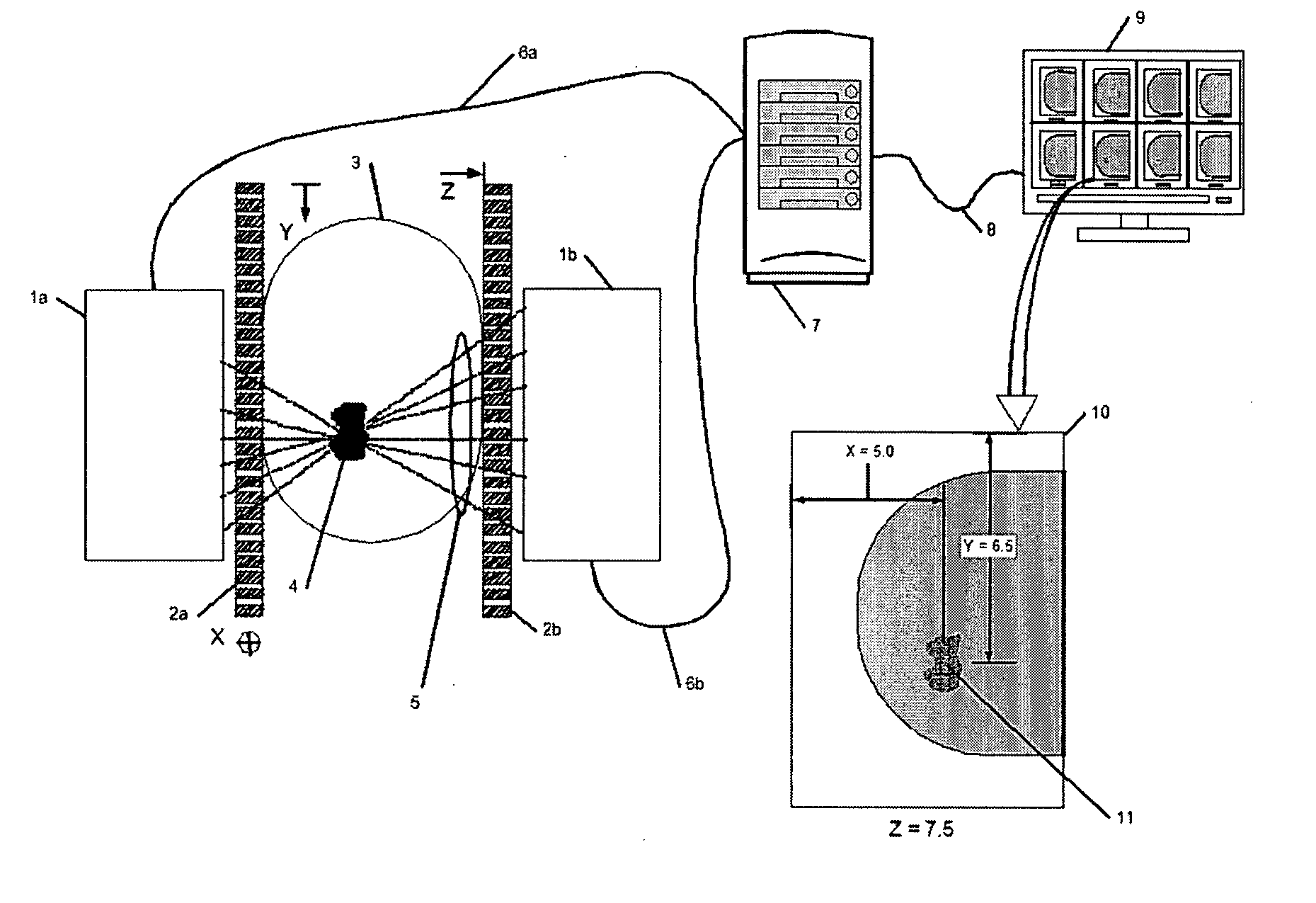
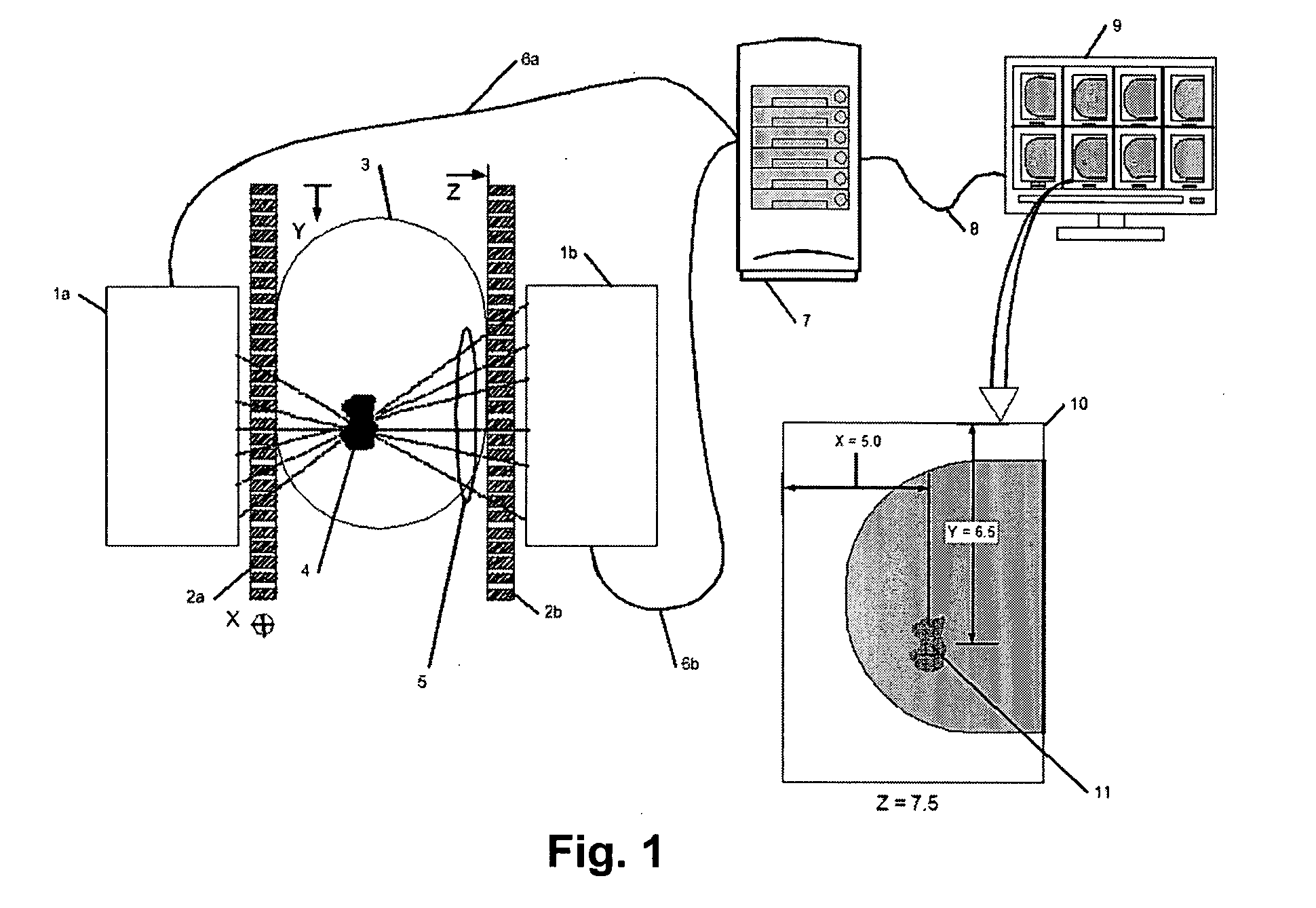
[0058] A purpose of the present invention is to provide a method and apparatus to enable nuclear emission guided interventions using an imager that is able to detect emissions from tissue. Preferably, the imager is also capable of providing spatial coordinates or demonstrating spatial positioning of suspect tissue, including tissue that is or is not compressed and / or immobilized.

[0059] Accordingly, the present invention provides a method for enabling nuclear-emission-guided interventions. The method includes the steps of: using a nuclear emission tomograph, determining the spatial coordinates of suspect tissue; and then positioning a radioactive marker at a location and orientation relative to the suspect tissue such that an intervention can be performed. A new image is then produced that demonstrates the location and orientation of the radioactive marker with respect to previously and simultaneously identified suspect tissue, which is used to confirm that the position and orientat...


PUM


Abstract

A method and apparatus for marking a lesion in a body part is provided. The method includes the steps of obtaining a first nuclear-emission image of the body part; determining a position of the lesion from the first image; percutaneously introducing a cannula to the determined position; inserting a wire into the cannula, the wire including radioactive material; retracting the cannula while holding the wire in place; and obtaining a second nuclear-emission image of the body part. The second image includes data relating to a position of the lesion and data relating to a position of the wire.

Description

CROSS-REFERENCE TO RELATED APPLICATIONS [0001] This application claims the benefit of U.S. Provisional Patent Application No. 60 / 692,243, entitled “Tissue Interventions Using Nuclear-Emission Image Guidance”, filed Jun. 21, 2005, the entire contents of which are expressly incorporated herein by reference.BACKGROUND OF THE INVENTION [0002] 1. Field of the Invention [0003] The present invention relates to an apparatus and a method for detecting and delineating cancerous lesions, and more particularly an apparatus and a method for effective and affordable early detection of cancerous lesions using gamma rays or other radiation to obtain image data. In addition, the present invention relates to applying contrast material to a medical device for the purpose of making it visible to imaging equipment and specifically to applying a radioactive contrast material to a medical device used for tissue marking, sampling, excision or therapy for the purpose of making it visible to nuclear-emission...

Claims


Application Information

Patent Timeline
Patent Type & Authority Applications(United States)
IPC IPC(8): A61B6/00H05G1/60
CPCA61B19/5244A61B19/54A61B2019/5238A61B2019/5408A61B6/037A61B2019/5433A61B2019/5487A61N2005/1052G01T1/2985A61B2019/542A61B2090/392A61B34/20A61B2090/376A61B90/39A61B2090/3908A61B2090/3933A61B2090/3987G01T1/29A61B6/00
Inventor YARNALL, STEPHEN T.BEYLIN, DAVIDHICKEY, LARRY
Owner COMPANIA MEXICANA DE RADIOLOGIA CGR S A DE
Why Eureka
Try Eureka