Self closing container

a self-closing, container technology, applied in the direction of lids, packaging, travelling articles, etc., can solve the problems of not providing for the use of travel mugs by persons lacking normal dexterity in hands and fingers, and the user's operation of the typical travel mug is difficult to achiev

Inactive Publication Date: 2007-07-26
CANEDO ROBERT
View PDF26 Cites 105 Cited by
  • Summary
  • Abstract
  • Description
  • Claims
  • Application Information

AI Technical Summary

Benefits of technology

[0008] When the handle or the outer sleeve is grasped and raised, the floating ring assembly is also raised. The floating ring assembly is magnetically bonded to the metallic upper portion of the outer sleeve via magnets affixed to its base. The magnets affixed to the base of the floating ring assembly are forcibly positioned into the proximity of corresponding magnets of opposite polarity extending through the openings of mouth platform. In addition, when floating ring is raised, mouth magnet platforms are raised. Mouth magnet platforms have two mouth magnets, one positioned toward mouth and one positioned toward the back of the lid. Also in this raised position mouth cover is moved backward to an open position with the use of the bar magnet component. When mouth magnets are raised, the magnetic field forces the bar magnet component back away from the mouth and toward the back of the lid. When the handle / outer sleeve is released, the opposite polarities of the lid and the ring magnets force the floating ring, its components and the mouth cover to their original positions.

Problems solved by technology

However, when a user lacks this normal dexterity, it is difficult to impossible for the user to operate the typical travel mug.
Unfortunately, the prior art does not provide for a travel mug to be used by persons lacking normal dexterity in their hands and fingers.

Method used


Image

  • Self closing container
  • Self closing container
  • Self closing container

Examples


Embodiment Construction

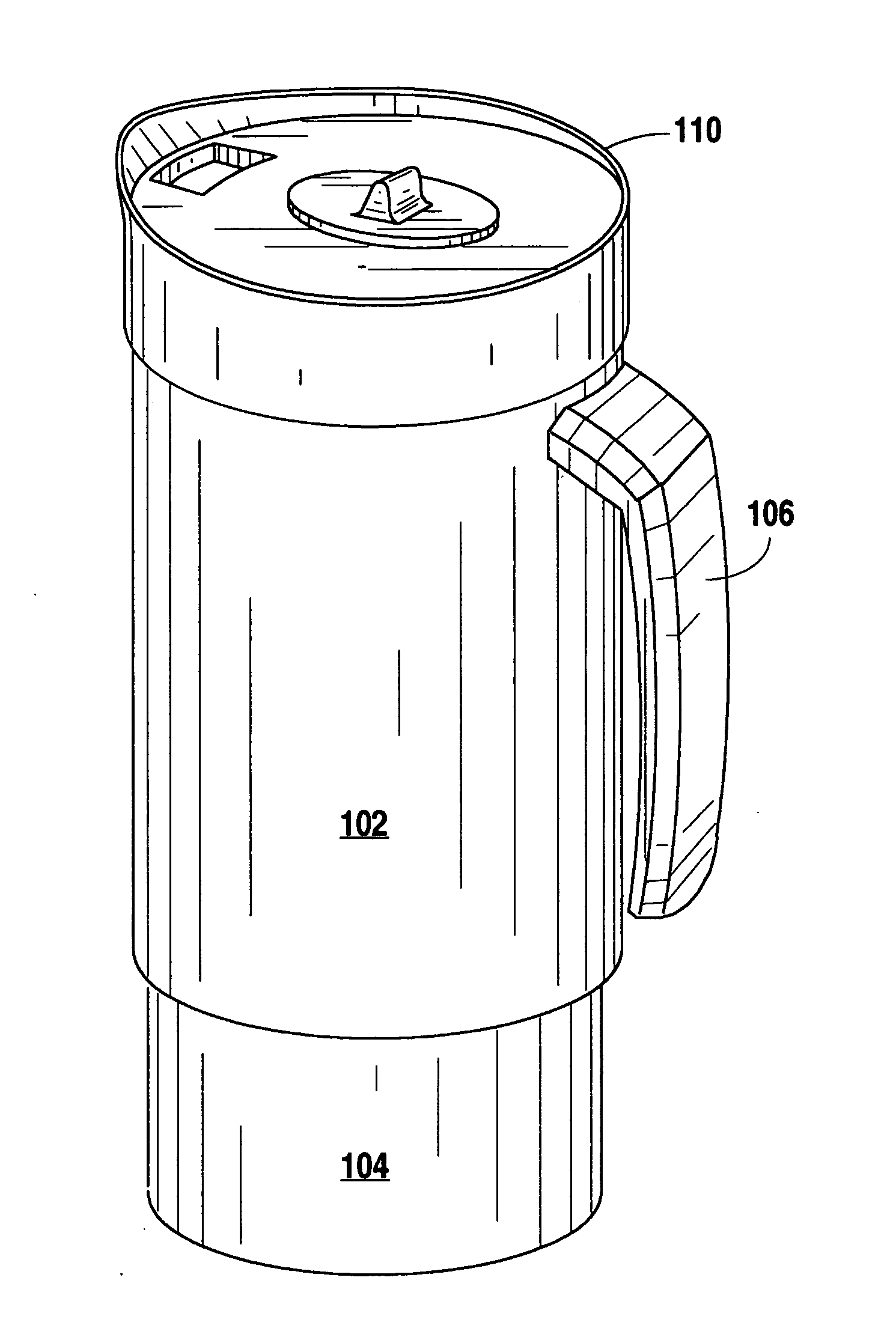
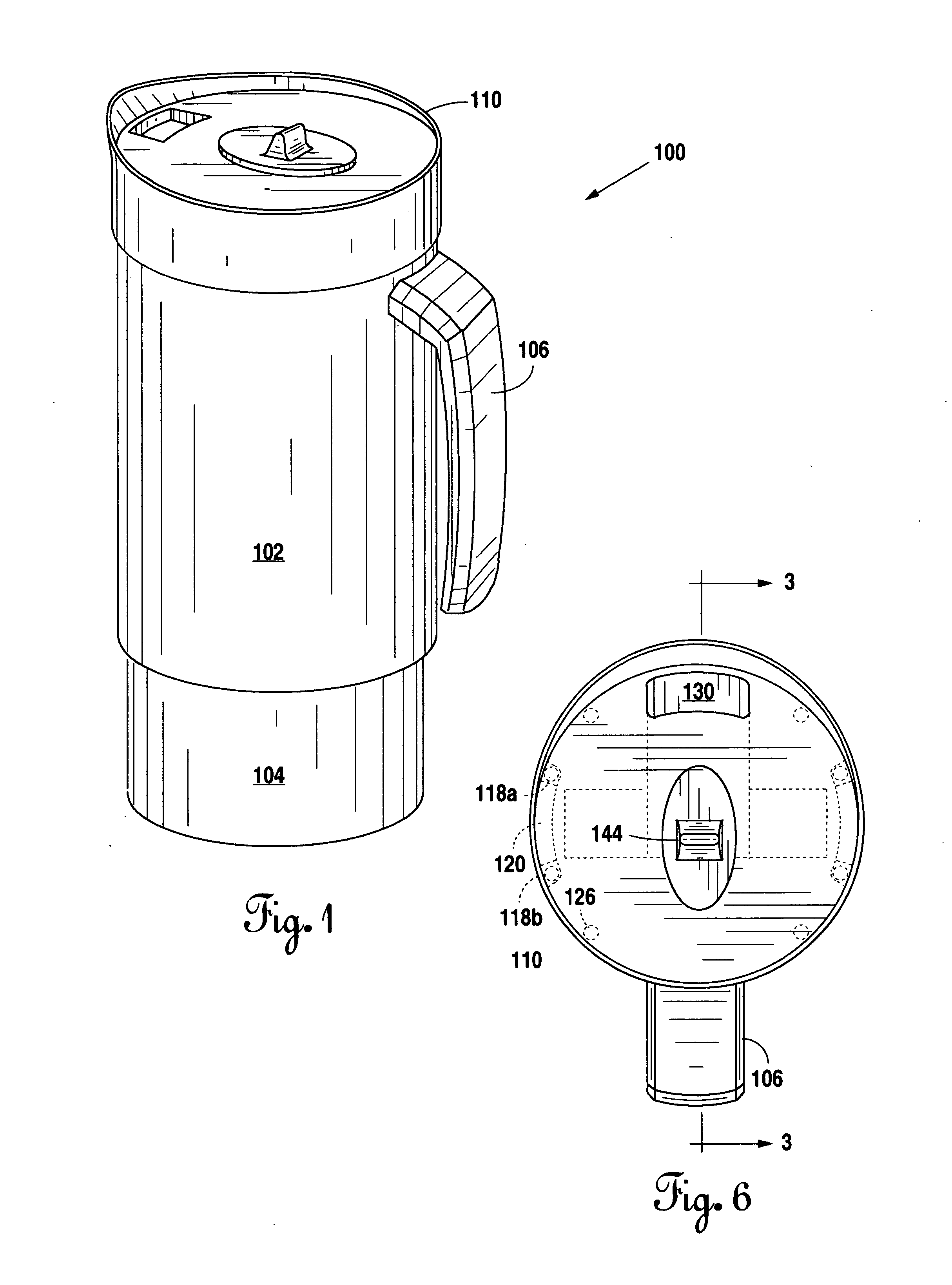
[0015] In FIG. 1, a perspective view of the preferred embodiment of the present self-closing container 100 is shown. The self-closing container 100 has an inner sleeve 104 designed to hold the contents of the container 100. Self closing container 100 also has an outer sleeve 102. A handle 106 is provided on outer sleeve 102. Container 100 also includes a lid 110 shaped to be removably secured to outer sleeve 102 and inner sleeve 104 via the rubber ring 112. This is the primary means of securing the lid 110. Securing the lid 110 with screw threads (not shown) is a viable alternative.

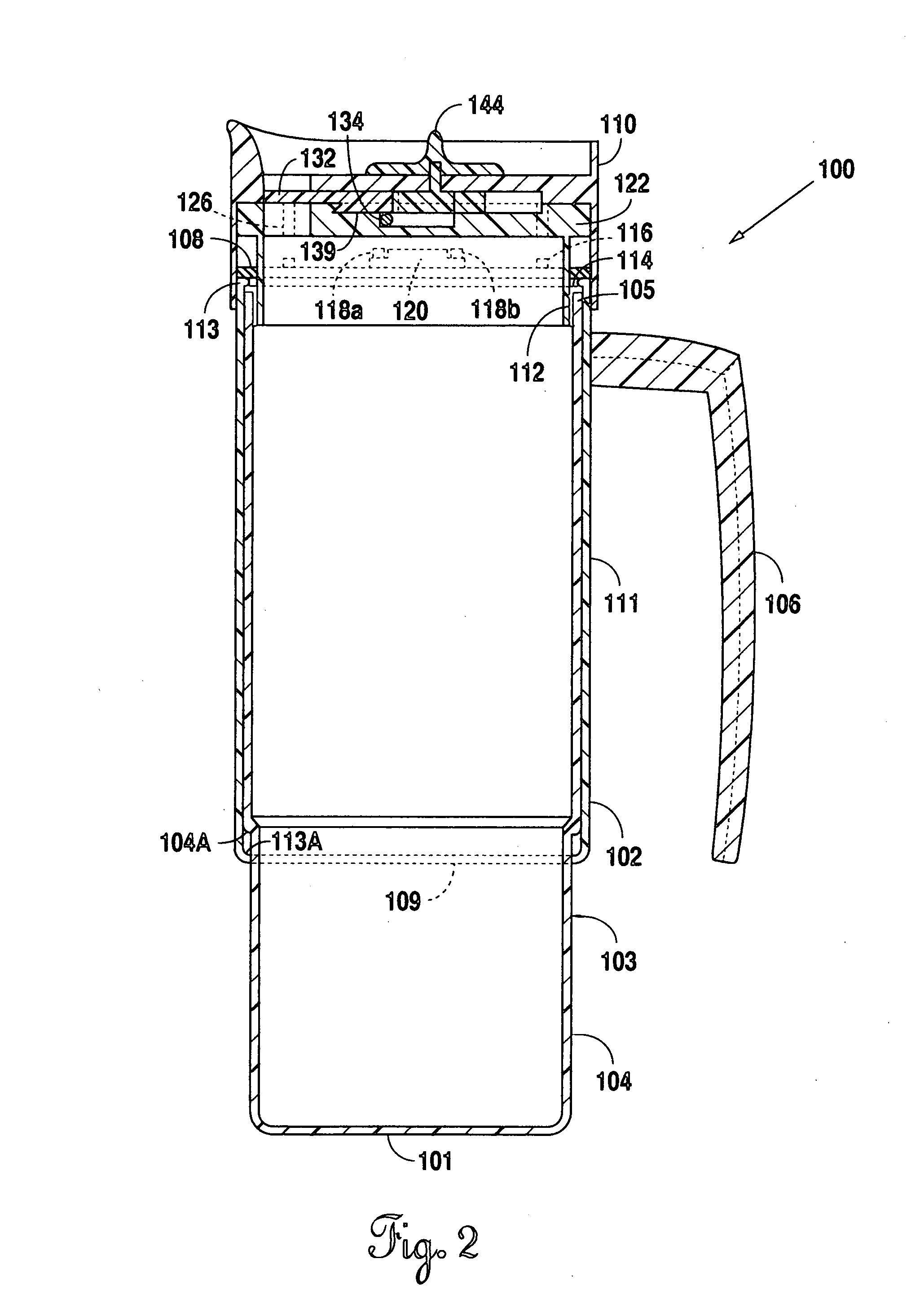
[0016]FIG. 2 is a side view of the preferred embodiment of the present invention with the lid closed. The self closing container 100 has an inner sleeve 104 which is designed to hold the contents of the container 100. The inner sleeve 104 is composed of a bottom 101, continuous side wall 103 and edge 105. An opening is provided across the edge 105. Self closing container 100 also has an outer sleeve 102....


PUM


Abstract

A self closing container having inner and outer sleeves. Outer sleeve surrounds inner sleeve and can freely slide on inner sleeve by lifting outer sleeve or handle. When container is closed, lid covers magnets, mouth magnets, mouth magnet platform, and mouth platform. When closed, bar magnet component is positioned over mouth magnets which permits mouth cover to cover mouth. When outer sleeve is raised, it raises ring in lid. In raised position, lid cover magnets on ring are repelled by corresponding magnets on lid cover. When ring is raised, mouth magnet platforms are raised. Mouth magnet platforms have two mouth magnets, one positioned toward mouth and one positioned toward back of the lid. When raised, mouth cover is moved backward to an open position with the use of the bar magnet component. When handle or outer sleeve is released all components return to their original positions effectively closing the container.

Description

BACKGROUND OF THE INVENTION [0001] 1. Field of the Invention [0002] Applicant's invention relates to a self closing container for liquids which prevents the liquid from spilling when jolted and allows a person to drink from an otherwise closed container. [0003] 2. Background Information [0004] Nowadays, it seems that everywhere you look someone is drinking out of a spill proof coffee mug or travel mug. The typical travel mug includes a container for holding the beverage fitted with a removable lid. The lid is generally provided with a mouth piece or opening through which the beverage may be removed by the user of the mug. This configuration allows considerable movement of the liquid within the mug without spilling because either the size of the opening in the lid or the mouth piece is such that it substantially confines the liquid. Recently developed travel mugs incorporate mouth covers over either the mouth opening or the mouth piece of the lid. The covers generally rest in a close...

Claims


Application Information

Patent Timeline
Patent Type & Authority Applications(United States)
IPC IPC(8): B65D51/18B65D51/00
CPCA45F3/18
Inventor CANEDO, ROBERT
Owner CANEDO ROBERT
Why Eureka
Try Eureka