Mail receptacle with delivery indicator

a technology of a receptacle and an indicator, which is applied in the direction of identification means, instruments, kitchen equipment, etc., can solve the problems of device not being able to adapt to other embodiments, device not being able to function,

Inactive Publication Date: 2007-07-26
NEFF RICHARD DEAN
View PDF32 Cites 68 Cited by
  • Summary
  • Abstract
  • Description
  • Claims
  • Application Information

AI Technical Summary

Benefits of technology

[0025] The present invention allows the user to detect the presence of mail or messages within the mailbox without having to approach the mailbox directly, use a remote control device to activate the indicator, or be inside the building or at the location where a separate indicator is positioned. Several embodiments of this invention are possible, including but not

Problems solved by technology

Such devices would not be readily adaptable to other embodiments.
If the current between the house and the unit should be interrupted for any reason, the device would not be able to function.
If the weight of the mail was not sufficient to trigger the signal, or if the flow of the current between the mailbox and the house was interrupted in any way, the device would not function.
Therefore it cannot be seen by approaching the multiple mailbox unit.
The indicator hangs down below the mailbox, making it difficult to see during the day and nearly impossible to see at night.
This device and others like it which are further detailed in other examples of prior art are intended mainly for rural mailboxes, which are positioned at the side of the road, and would not be readily adaptable to other embodiments.
This system would not work with a mailbox in which mail is deposited through a slot.
U.S. Pat. No. 7,066,381 describes a system incorporating a flag

Method used


Image

  • Mail receptacle with delivery indicator
  • Mail receptacle with delivery indicator
  • Mail receptacle with delivery indicator

Examples


Embodiment Construction

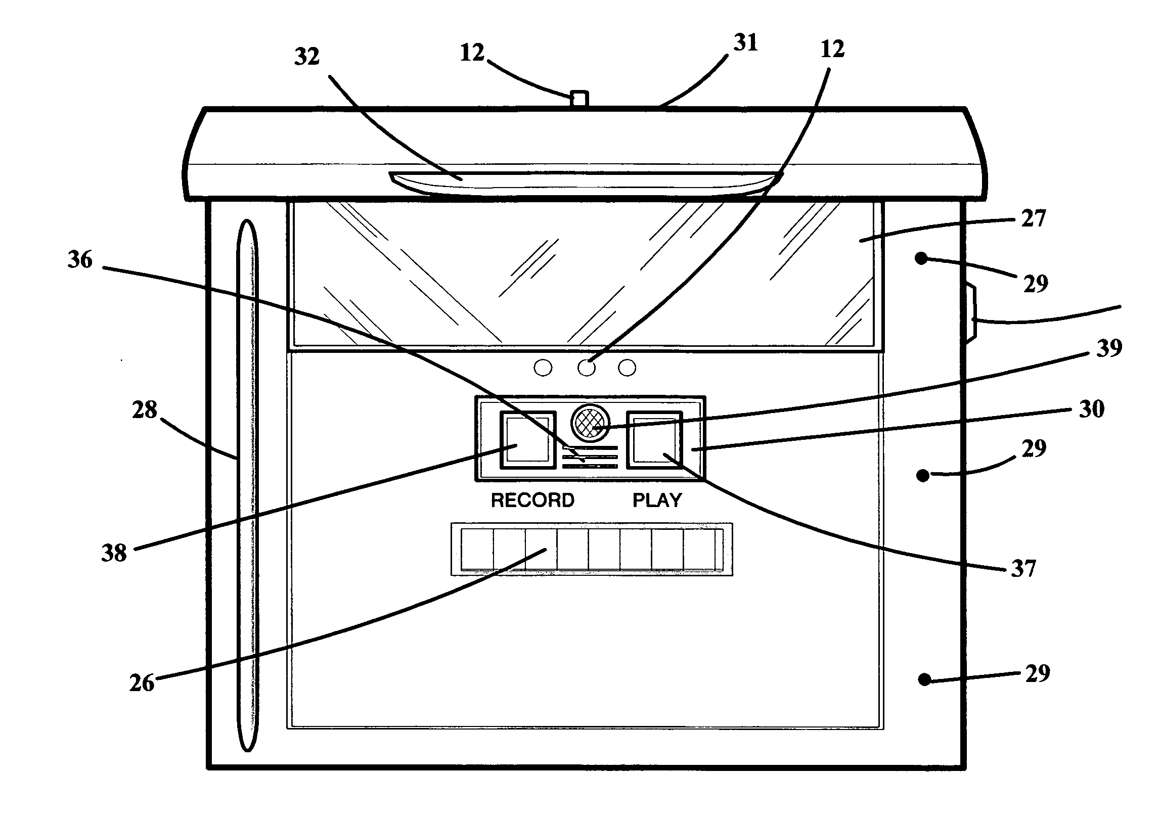
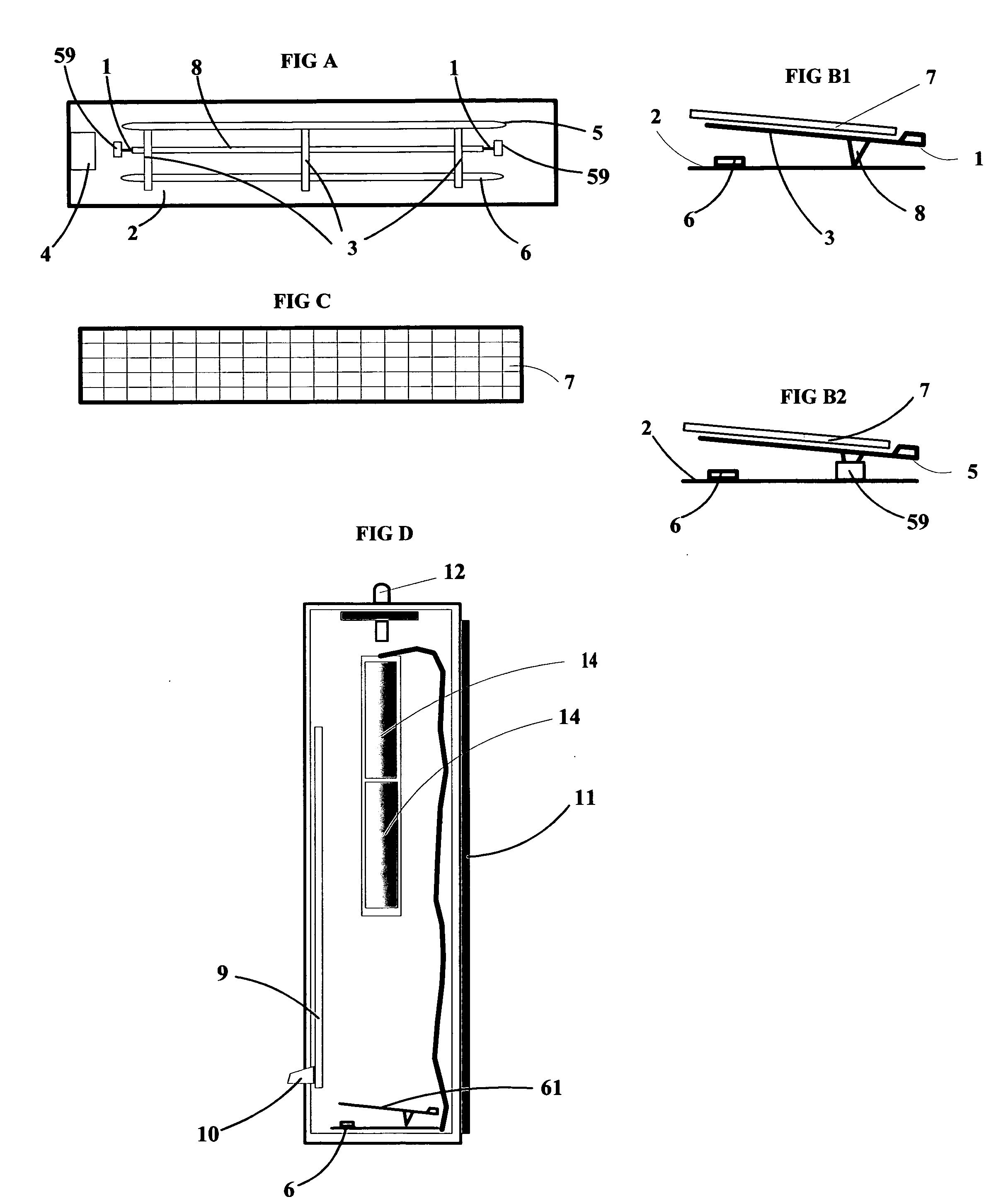
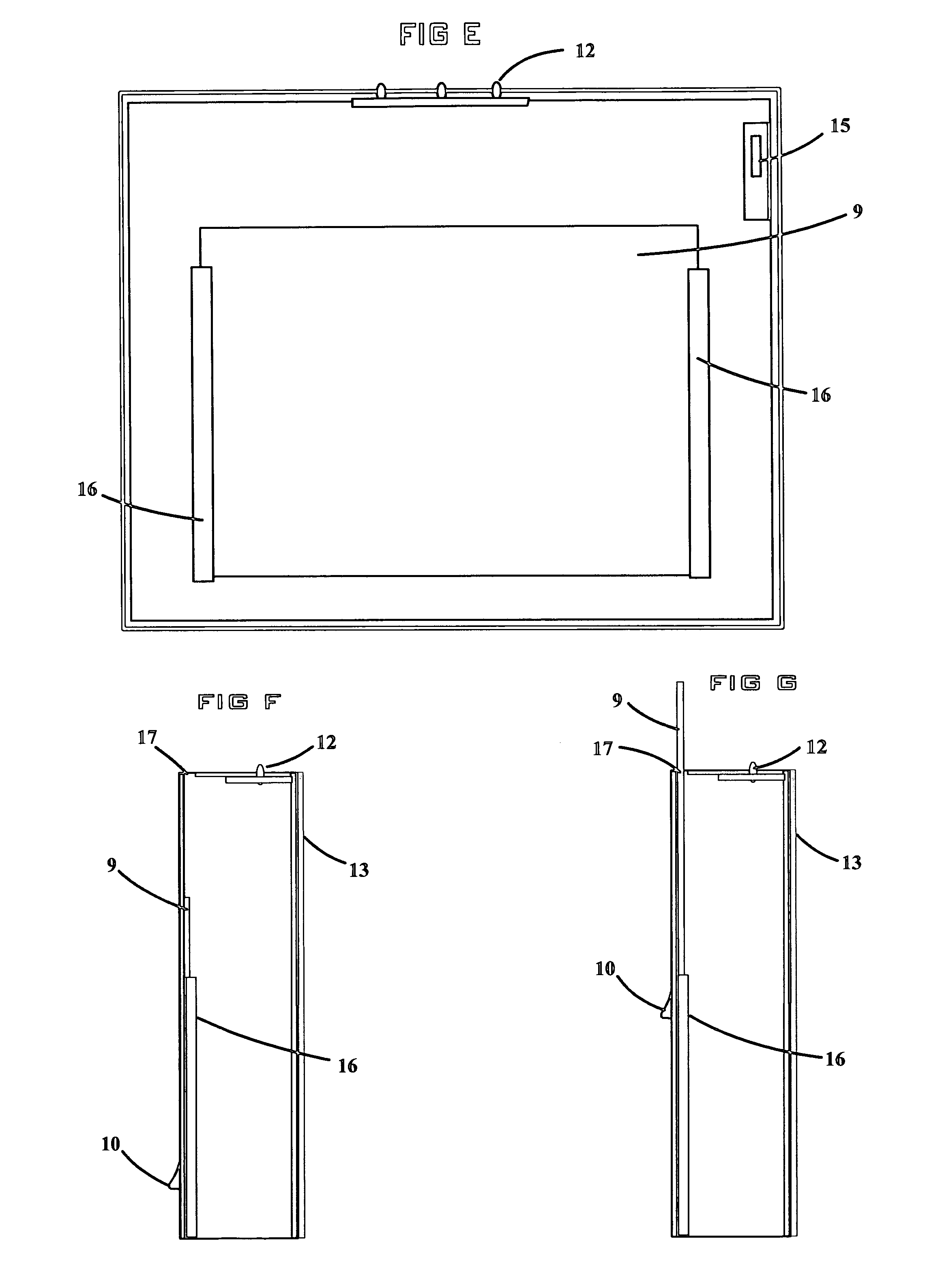
[0129] The preferred embodiment is a unit that will allow easier communication between school students, or anyone else who makes regular use of a wall locker. Said unit could be used in school lockers, sports lockers, industrial locker rooms, or any location where the same person occupies the same locker for an extended period of time. In this embodiment said unit is attached to the inside of said wall locker, using magnetic strips that will hold it securely in place on the metal door of said wall locker. Said magnetic strips could vary in size, depending on the size of the unit, the main requirement being that they need to be large enough to support the weight of said unit on the inside of said door of said wall locker. Other means of attachment could be used apart from or in combination with said magnetic strips. These means of attachment could include, but are not limited to, one or a plurality of suspending means attached to said unit, which would fit over one or more of the ven...


PUM


Abstract

The “Mail Receptacle with Delivery Indicator” is a device which will allow the user of the unit to visually detect the presence of mail without opening the unit, or even approaching said unit directly. There are several possible embodiments of said device, including but not limited to a unit which can be placed at the roadside in rural areas for delivery of mail, a unit which can be mounted on the outside wall of a house for delivery of mail in urban areas, a smaller unit, possibly assembled in groups, which could be used for multiple dwellings such as apartment complexes, a special unit to be placed inside a wall locker in a school, factory, or any other location in which wall lockers are used, or a decorative unit which could be placed on a desk or table to be used for personal or interoffice communication. The unit may also include a recording means which would allow a verbal message for the user of the mailbox to be recorded and played back at the convenience of the user. The unit may also include a security mechanism which prevents unauthorized persons from having access to mail within the unit. The unit may also include a protected area for displaying the name and/or house number of the user, providing easier identification of the proper unit for someone delivering mail.

Description

[0001] This utility patent application claims priority of provisional patent application 60 / 759925 filed Jan. 19, 2006, which is incorporated by reference herein.FIELD OF THE INVENTION [0002] The present invention relates to devices and systems for detecting the presence of verbal or written communication in a receptacle intended to receive such communication. More particularly, the invention relates to devices and systems for detecting the presence of such communications without the need to open the receptacle. The invention also relates to protection of such communications from unauthorized users, and more easily identifying the proper receptacle to receive such communications. REFERENCES CITED [0003]U.S. Patents1.4,101,877July 1978Rush2.4,154,393May 1979Darvishan3.4,314,102Febuary 1982Lowe & McFiggans4.4,633,236June 1985Buhl & Holger5.4,999,612March 1991Cherveny6.5,040.723August 1991Kelly7.5,239,305August 1993Murphy & Shea8.5,335,848August 1994Schreiber9.5,382,945January 1995Nova...

Claims


Application Information

Patent Timeline
IPC IPC(8): A47G29/12
CPCG09F9/33A47G29/122
Inventor NEFF, RICHARD DEAN
Owner NEFF RICHARD DEAN
Why Eureka
Try Eureka