Eureka AIR delivers breakthrough ideas for toughest innovation challenges, trusted by R&D personnel around the world.

Device for sealing a gap between car door and car wall in an elevator car

Inactive Publication Date: 2007-07-26
INVENTIO AG
View PDF27 Cites 7 Cited by
  • Summary
  • Abstract
  • Description
  • Claims
  • Application Information

AI Technical Summary

Benefits of technology

[0006] The present invention has the object of creating a device which does not have the stated disadvantages and substantially eliminates gaps between the car door and the car wall. In particular, there shall be created a sealing device with simple construction that operates independently of the door movement.
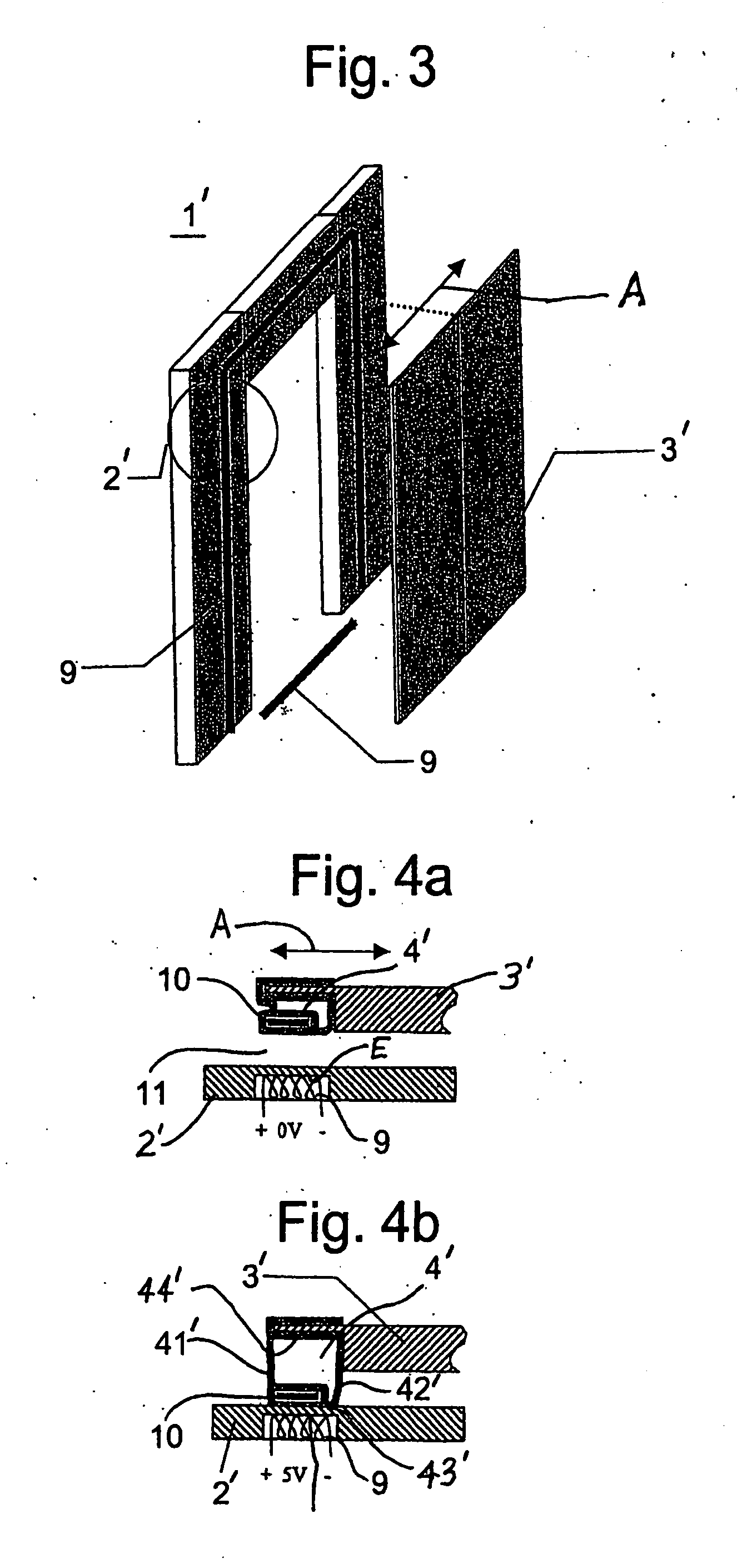
[0010] According to a second embodiment the sealing strip advantageously comprises iron strips and at least one electromagnetic, which is electrically activated. The advantages achieved by this embodiment are that due to the simple construction of the sealing device large savings in technical outlay are achieved and that due to the simple construction there is ensured a minimum susceptibility to fault. A further advantage consists in that due to the independence from the door motion a more rapid mode of operation of the sealing device is possible. A further advantage consists in that the effectiveness of the sealing device is substantially improved.
[0011] The present invention resolves a long-standing prejudice of the elevator expert world, according to which no additional components are to be arranged at the elevator car in order to save weight and costs. In this specific case, however, hollow bodies or electromagnets are arranged around the car opening of an elevator car. Moreover, compressed air lines or vacuum lines are required. It has unexpectedly proved that these components are light and economic and enable a significant improvement in travel comfort and a noticeable simplification of the mechanical structures for sound insulation in elevator cars.

Problems solved by technology

In high-speed elevator cars the problem exists of sound insulation, because with increasing travel speed the travel and air noises produced in the shaft progressively increase, penetrate through every opening into the car interior and thus reduce travel comfort.
However, acoustic experiments show that the smallest openings admit a considerable amount of sound.
This is an expensive method and not satisfactory in effect.
It is shown in the U.S. Pat. No. 3,425,162 that this problem is not usually given any consideration and consequently these gaps are not sealed at all.
A disadvantage of this known equipment resides in the substantial mechanical outlay and the large production costs connected therewith.
A further disadvantage is the high expenditures on adjustment and maintenance operations.

Method used


Image

  • Device for sealing a gap between car door and car wall in an elevator car
  • Device for sealing a gap between car door and car wall in an elevator car
  • Device for sealing a gap between car door and car wall in an elevator car

Examples


Embodiment Construction

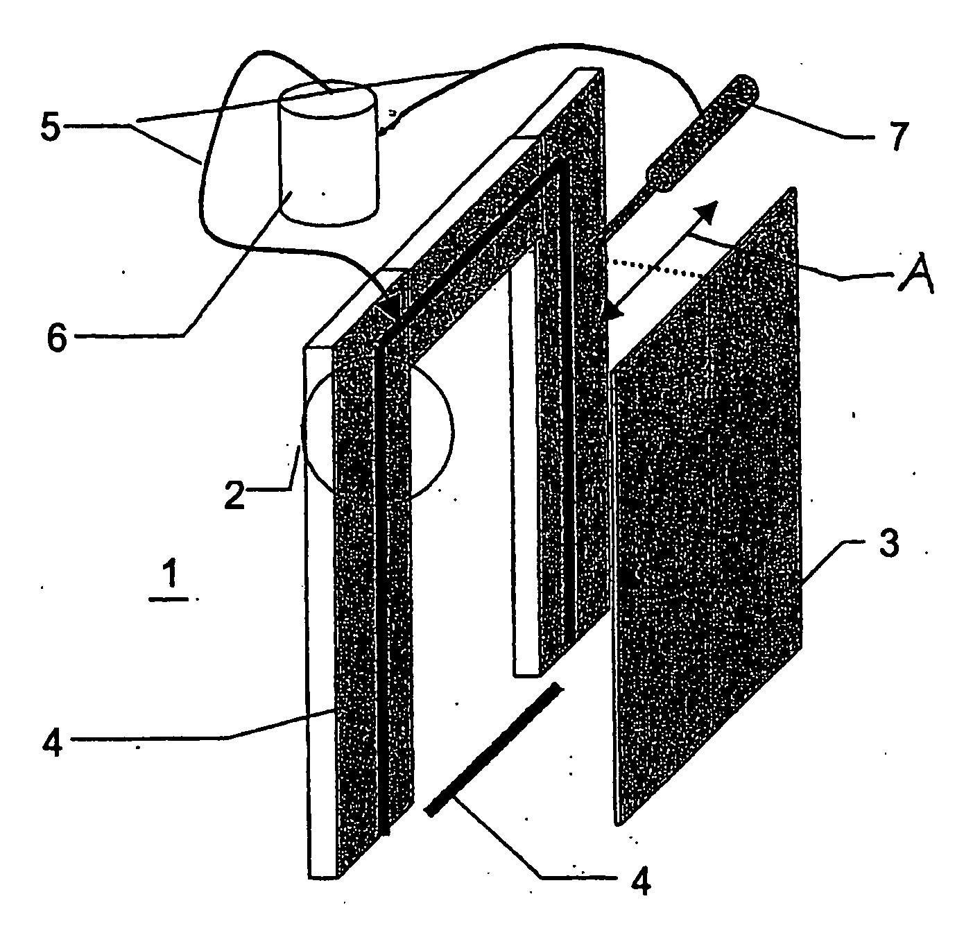
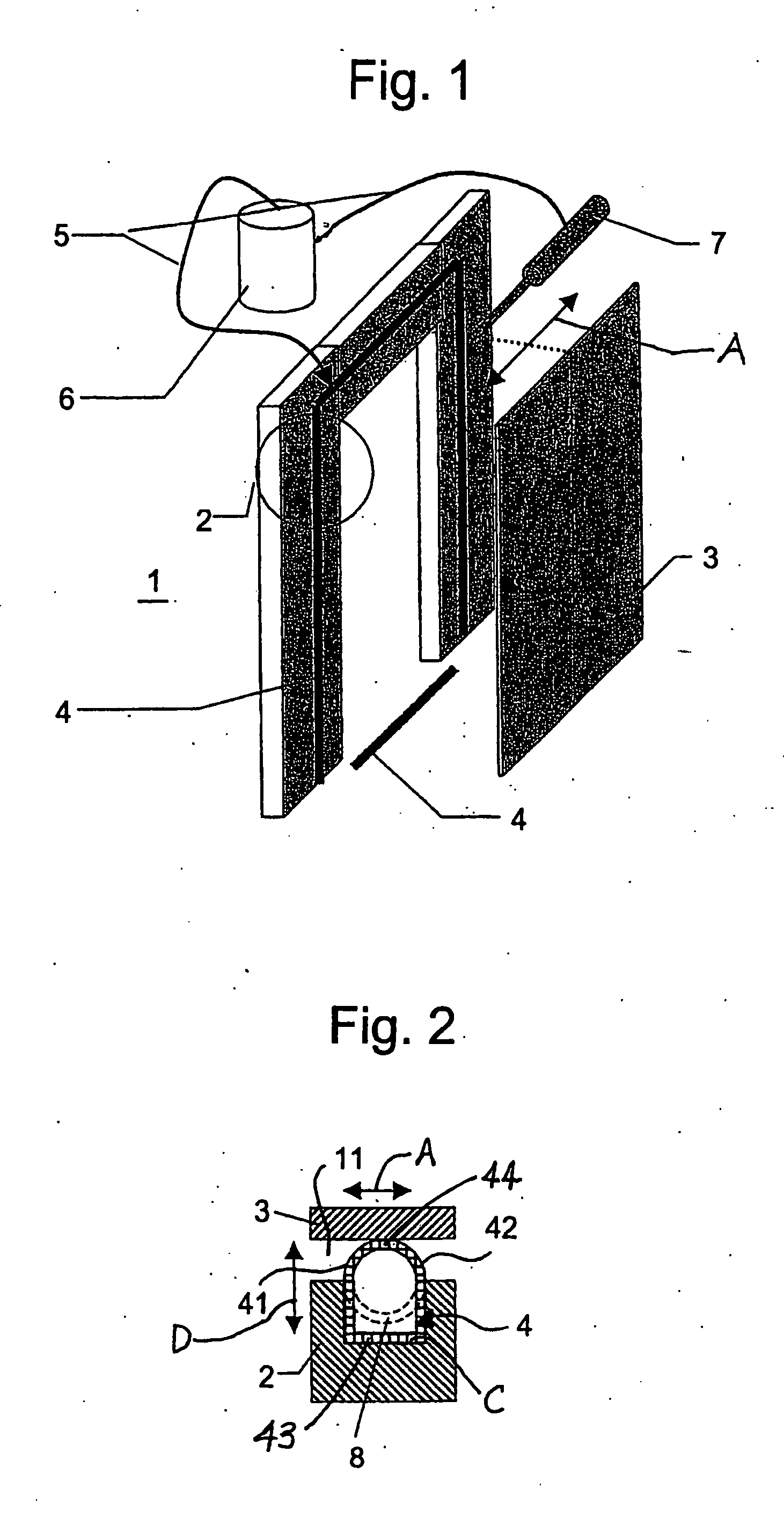
[0018] As shown in FIGS. 1 and 2, an elevator car 1 has a car wall denoted by 2 and an associated car door denoted by 3. The door 3 moves along a path parallel to the wall 2 as shown by an arrow A to open and close a door opening B formed in the wall. A sealing strip 4 made of resilient material is arranged around the car door opening B. The sealing strip 4 consists of an upper part and a lower part (in the threshold), which have a generally annular cross-section in a relieved state as illustrated in FIG. 2 by dashed lines. The sealing strip 4 consists of a hollow body 8 that is retained in a groove C formed in a surface of the wall 2 facing the door 3. When the sealing strip 4 is in an actuated state, as shown in solid lines in FIG. 2, it resiliently expands in a balloon-like manner to form a first wall portion 41 and a parallel second wall 42 sealingly contacting opposing walls of the groove C. A third wall portion 43 sealingly contacts a bottom wall of the groove C and a fourth w...


PUM


Abstract

An apparatus for sealing a gap between an elevator car door and the associated car wall during car travel includes a sealing strip of resilient material with wall portions that can be reversibly stretched to bridge and seal the gap.

Description

BACKGROUND OF THE INVENTION [0001] The present invention relates to a device for sealing a gap between a car door and a wall of an elevator car. [0002] In high-speed elevator cars the problem exists of sound insulation, because with increasing travel speed the travel and air noises produced in the shaft progressively increase, penetrate through every opening into the car interior and thus reduce travel comfort. Usual sound insulation with insulating material fillings in double-walled walls and doors, as well as quietly operating ventilation systems, are capable of achieving, in conjunction with vibration damping devices, an appropriate effect. However, acoustic experiments show that the smallest openings admit a considerable amount of sound. With respect to a door this means that a door gap of at least one percent of the entire door opening cross-section lets through a third towards a half the volume of sound, which is generated outside this door, to the other side, thus into the ca...

Claims


Application Information

Patent Timeline
IPC IPC(8): F16J15/46E06B7/18B66B11/02B66B13/30E06B7/22E06B7/23
CPCB66B13/30E06B7/2318B66B13/308
Inventor KUIPERS, ERWIN REINDEROBERER, ALEXAUGUGLIARO, DARIO
Owner INVENTIO AG
Why Eureka
Eureka Blog
Learn More