3D lithography with laser beam writer for making hybrid surfaces

Active Publication Date: 2007-08-02
PANASONIC CORP
View PDF7 Cites 23 Cited by
  • Summary
  • Abstract
  • Description
  • Claims
  • Application Information

AI Technical Summary

Benefits of technology

[0005] Another exemplary embodiment of the present invention is a method of etching a feature in a mold surface of a mold part. A photoresist layer is formed on the mold surface of the mold part. A thickness profile of the formed photoresist layer is determined. A grayscale scanning pattern is determined based on the feature and the thickness profile of the photoresist layer. The determined grayscale scanning pattern is laser written on the

Problems solved by technology

However, direct e-beam writing is both slow and costly, and also the precision of the grayscale features (e.g., the height of each step of the grayscale features) is based on how precisely the scan rate and

Method used


Image

  • 3D lithography with laser beam writer for making hybrid surfaces
  • 3D lithography with laser beam writer for making hybrid surfaces
  • 3D lithography with laser beam writer for making hybrid surfaces

Examples


Example

[0015] Although the invention is illustrated and described herein with reference to specific embodiments, the invention is not intended to be limited to the details shown. Rather, various modifications may be made in the details within the scope and range of equivalents of the claims and without departing from the invention.

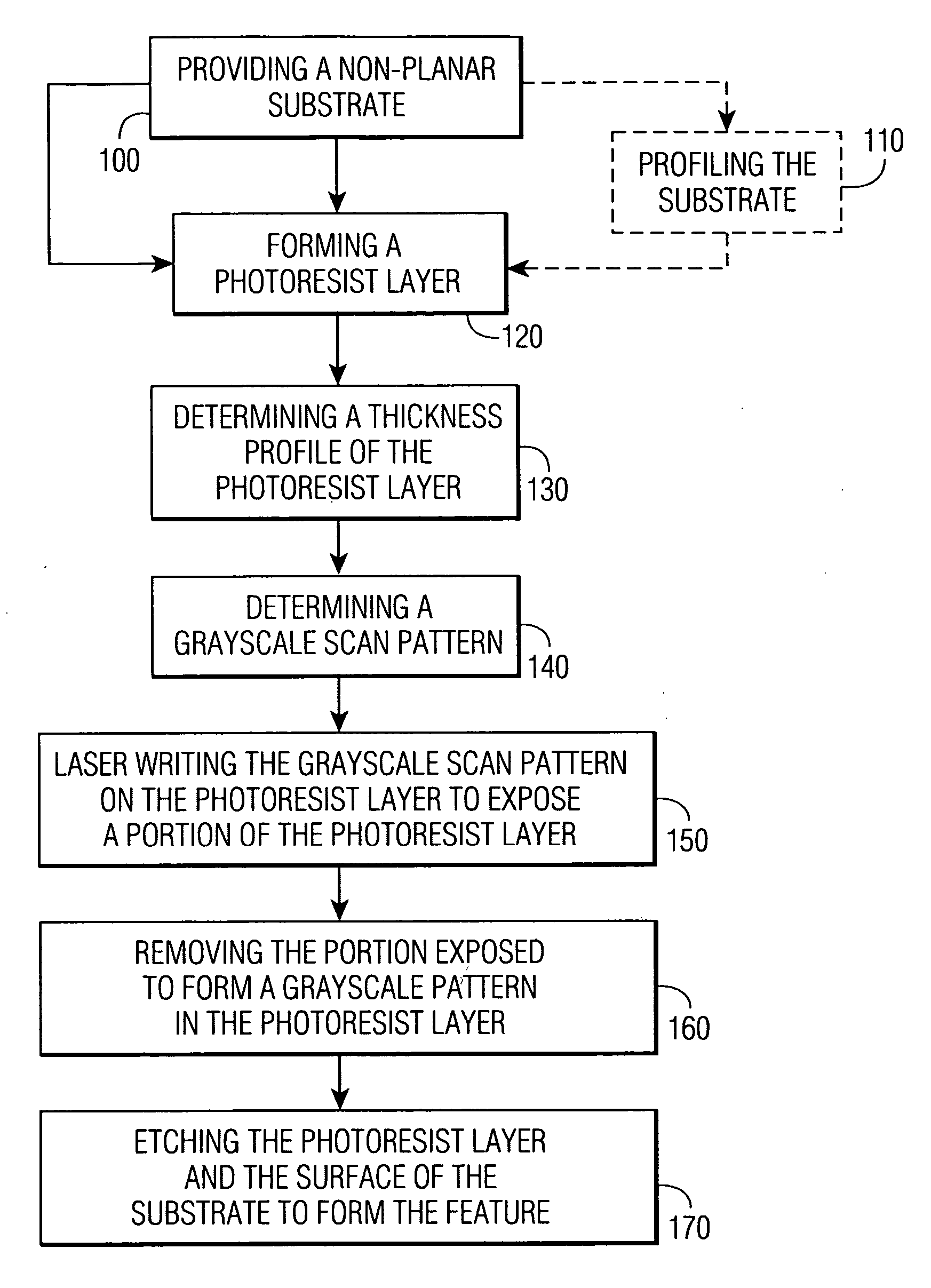
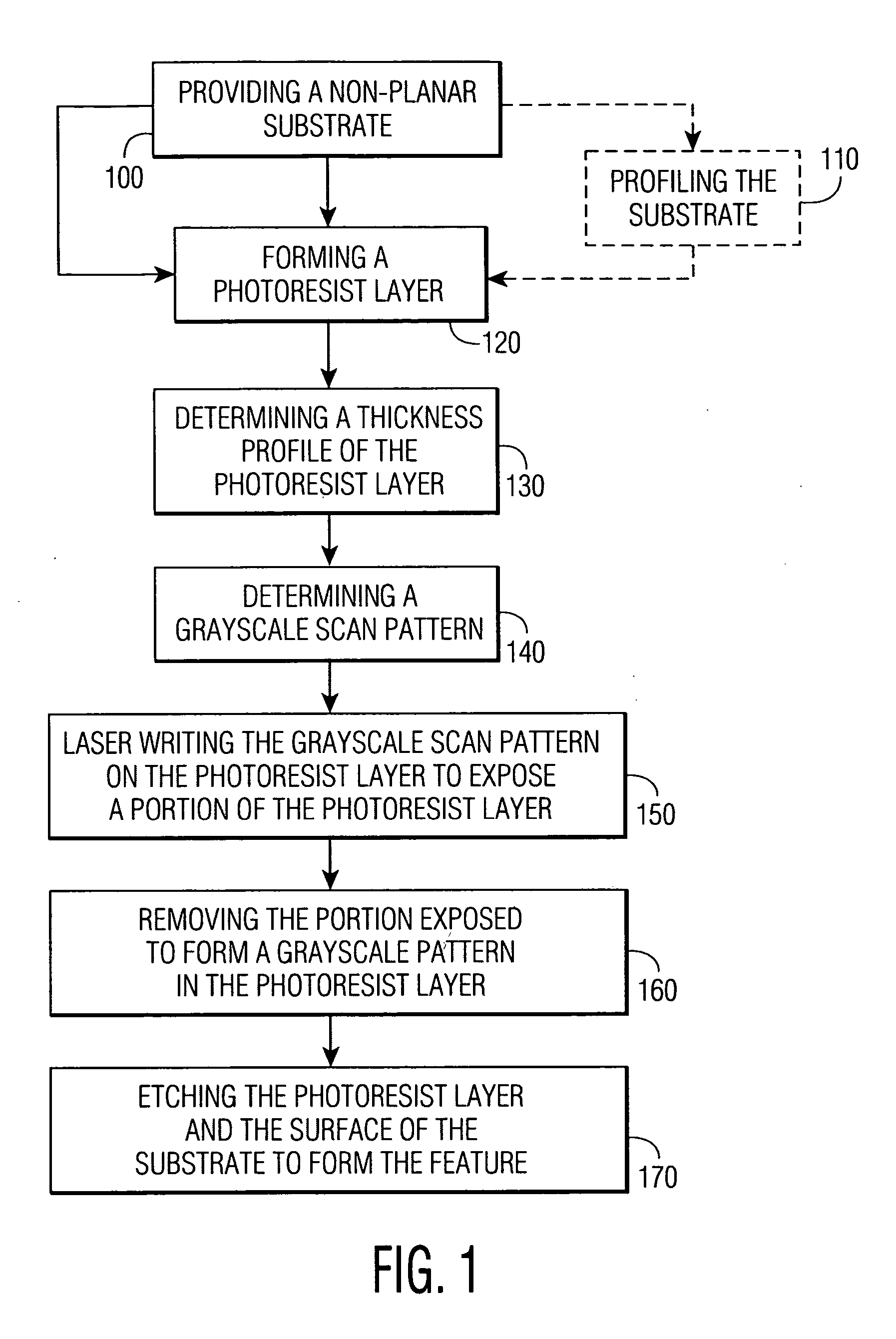
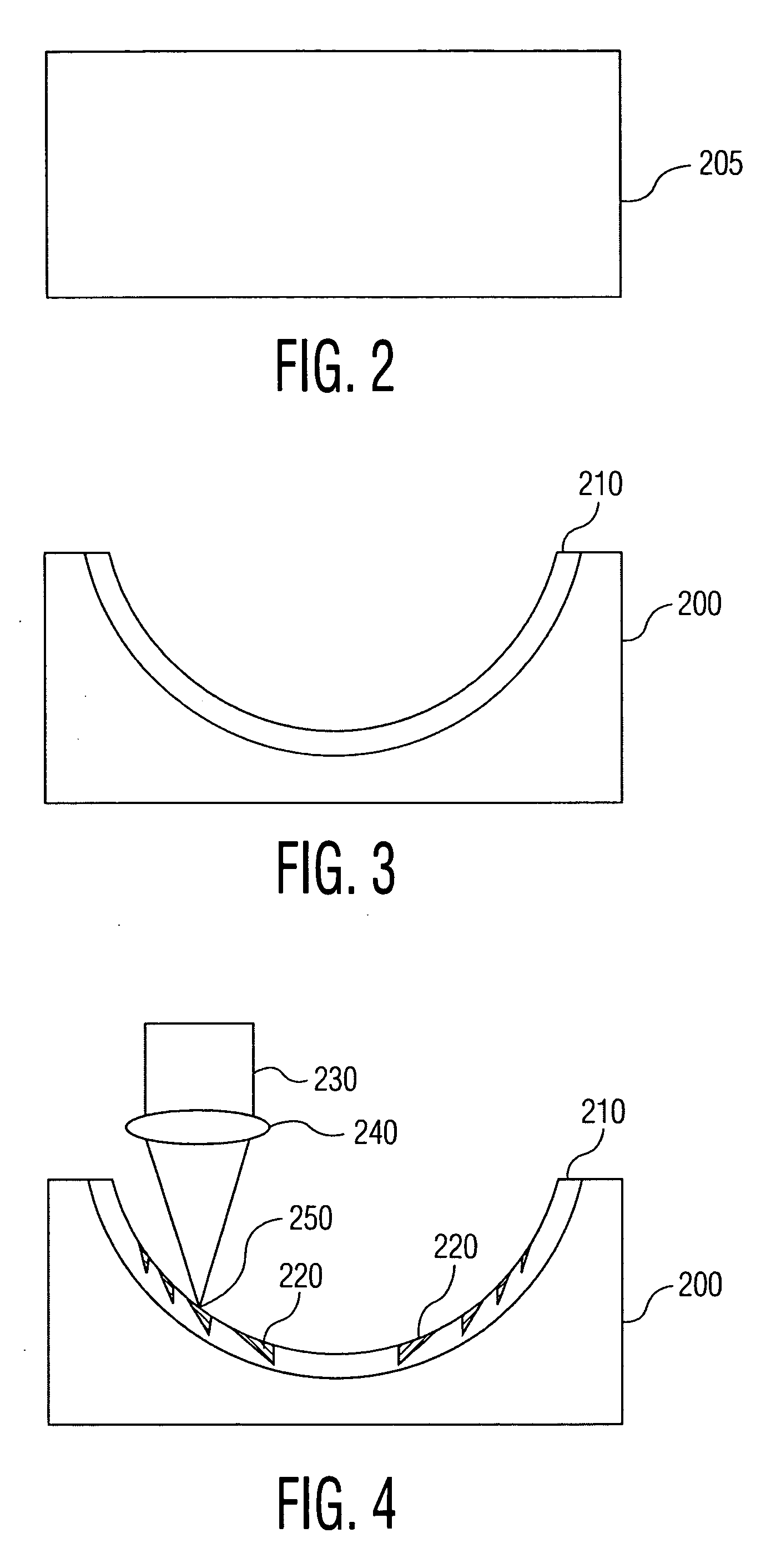
[0016]FIG. 1 is a flowchart illustrating a method of etching a feature on a surface of a substrate in accordance with an exemplary embodiment of the present invention. FIGS. 2-7 are cross-sectional side views of an exemplary substrate illustrating the steps the exemplary method shown in FIG. 1.

[0017] Referring now to FIGS. 2-7, in exemplary embodiments of the invention, a feature 270 of a non-planar substrate 200 (as shown in FIG. 7) may be realized, for example, by: (1) laser-writing-a grayscale scanning pattern corresponding to feature 270 to be etched on the surface of substrate 200 on a photoresist layer 210 (as shown in FIG. 4) to expose a portion of photo...


PUM

PropertyMeasurementUnit
Thicknessaaaaaaaaaa
Poweraaaaaaaaaa
Widthaaaaaaaaaa

Abstract

A method of etching a feature in a surface of a substrate. The substrate is provided. A photoresist layer is formed on the surface of the substrate. A thickness profile of the formed photoresist layer is determined. A grayscale scanning pattern is determined based on the feature and the thickness profile of the photoresist layer. The determined grayscale scanning pattern is laser written on the photoresist layer to expose a portion of the photoresist layer. The exposed portion of the photoresist layer is removed to form a grayscale pattern in the photoresist layer. The photoresist layer and the surface of the substrate are etched to form the feature in the surface of the substrate.

Description

FIELD OF THE INVENTION [0001] The invention relates to methods of lithography using a laser beam writer to produce features in a substrate and, more particularly, to a method of producing desired three dimensional features in a substrate. BACKGROUND OF THE INVENTION [0002] Direct e-beam (electron-beam) milling has been used conventionally to produce grayscale features in a substrate by directing an electron beam towards the substrate in a scanning pattern and either modulating the intensity of the electron beam or the scan rate across the substrate such that a grayscale pattern is produced in the substrate as grayscale features. However, direct e-beam writing is both slow and costly, and also the precision of the grayscale features (e.g., the height of each step of the grayscale features) is based on how precisely the scan rate and / or the intensity of the e-beam are set. The use of lower intensities and commensurately lower scan rates may improve the precision with which these param...

Claims


Application Information

Patent Timeline
IPC IPC(8): C23F1/00B44C1/22H01L21/302C03C25/68
CPCG02B5/1852G02B5/1895G03F7/0005H01L21/308G03F7/24H01L21/0275G03F7/0017
Inventor LIU, XINBING
Owner PANASONIC CORP
Why Eureka
Try Eureka