Compression coil spring device having a discrete support

a compression coil spring and discrete support technology, applied in the direction of springs/dampers, wound springs, mechanical equipment, etc., can solve the problems of increasing the spring load, reducing the number of effective turns of the coil spring, and the ineffective production of spring force by the close wound turn and ground end, so as to minimize the variation in the spring property, minimize the spring force, and minimize the effect of friction resistan

Inactive Publication Date: 2007-08-02
NHK SPRING CO LTD
View PDF5 Cites 2 Cited by
  • Summary
  • Abstract
  • Description
  • Claims
  • Application Information

AI Technical Summary

Benefits of technology

[0016] Thus, the spring demonstrates a same property, with reference to the centroid of contact pressure or line of action of the spring force and the spring constant, without regard to the spring load as long as the spring end is supported by the same discrete contact point or points. In other words, the changes in the number of effective turns depending on the magnitude of the load can be minimized over a certain range so that the relationship between the load and compression stroke can be made substantially linear over this range, and the change in the angle of the axis of the spring force can be minimized. Also, in the above structure, the end turn contacts the spring seat only at the predetermined projections, and this minimizes the variation in the spring property, frictional resistance between the contacting members and bending moment relating to individual coil springs.
[0017] For instance, when tuning a wheel suspension system, it is important to tune it optimally under a most common situation such as when the vehicle is cruising on a relatively flat highway. According to the present invention, by properly selecting the positioning of the discrete support points of the end turn of the coil spring in relation with the weight of the vehicle and property of the spring, it is possible to achieve a linear behavior of the coil spring around the neutral operating point of the coil spring as well as to minimize the variation in the property of coil springs associated with respective wheels. By optimally tuning the wheel suspension system with respect to this linear operating range of the coil spring and minimizing the spring property variation, the wheel suspension system may become capable of achieving a highly desirable ride quality.

Problems solved by technology

However, the entire contact surface of the closely wound turn and ground end may not contact an opposing member, such as a spring seat, but instead, they tend to contact the opposing member partially at unpredictable points, which can result in a varying spring property or varying relationship between the load and the compression stroke.
Also the closely wound turn and ground end are not effective in producing the spring force.
Also, because the part of the coil wire which is in contact with the spring seat is not capable of any further deflection, and is, therefore, ineffective in increasing the spring force, an increase in the contacting part between the coil wire and the spring seat resulting from an increase in the spring load means a decrease in the number of effective turns of the coil spring.
In many applications, such changes in the spring property with the change in the spring load are not desirable.
For instance, in a strut wheel suspension system for motor vehicles, because the point of input of the force which pushes up the tire does not agree with the axial line of the linear hydraulic damper due to the problems associated with the vehicle body structure and the convenience of assembly work, as the tire moves vertically, a certain bending moment is produced in the damper.
This bending moment increases the frictional resistance between the damper tube and the piston and between the piston rod and rod guide, and hampers the smooth telescopic motion of the damper.
This not only impairs the ride quality but also adversely affects the durability of the sliding parts.
In addition, because individual coil springs may have different specifics, the decrease in the number of effective turns may occur in different fashions for different coil springs, leading to varying compression property.
This may result in a coil spring which does not contribute to the action of improving the ride quality.
However, if the spring property varies depending on the spring load or the compression stroke, any exact tuning becomes impossible.
This is a problem not only for the springs of wheel suspension systems but also for other applications where any tuning of the spring property is required.

Method used


Image

  • Compression coil spring device having a discrete support
  • Compression coil spring device having a discrete support
  • Compression coil spring device having a discrete support

Examples


Embodiment Construction

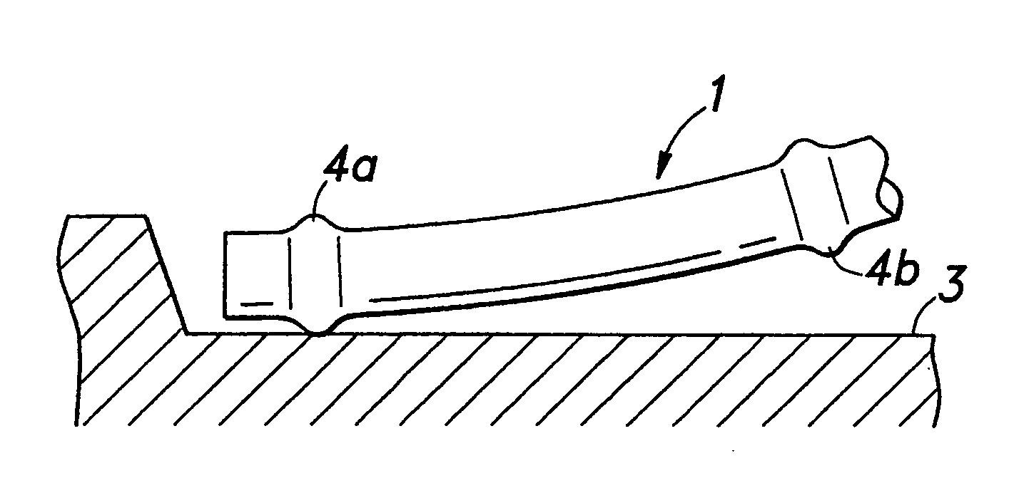
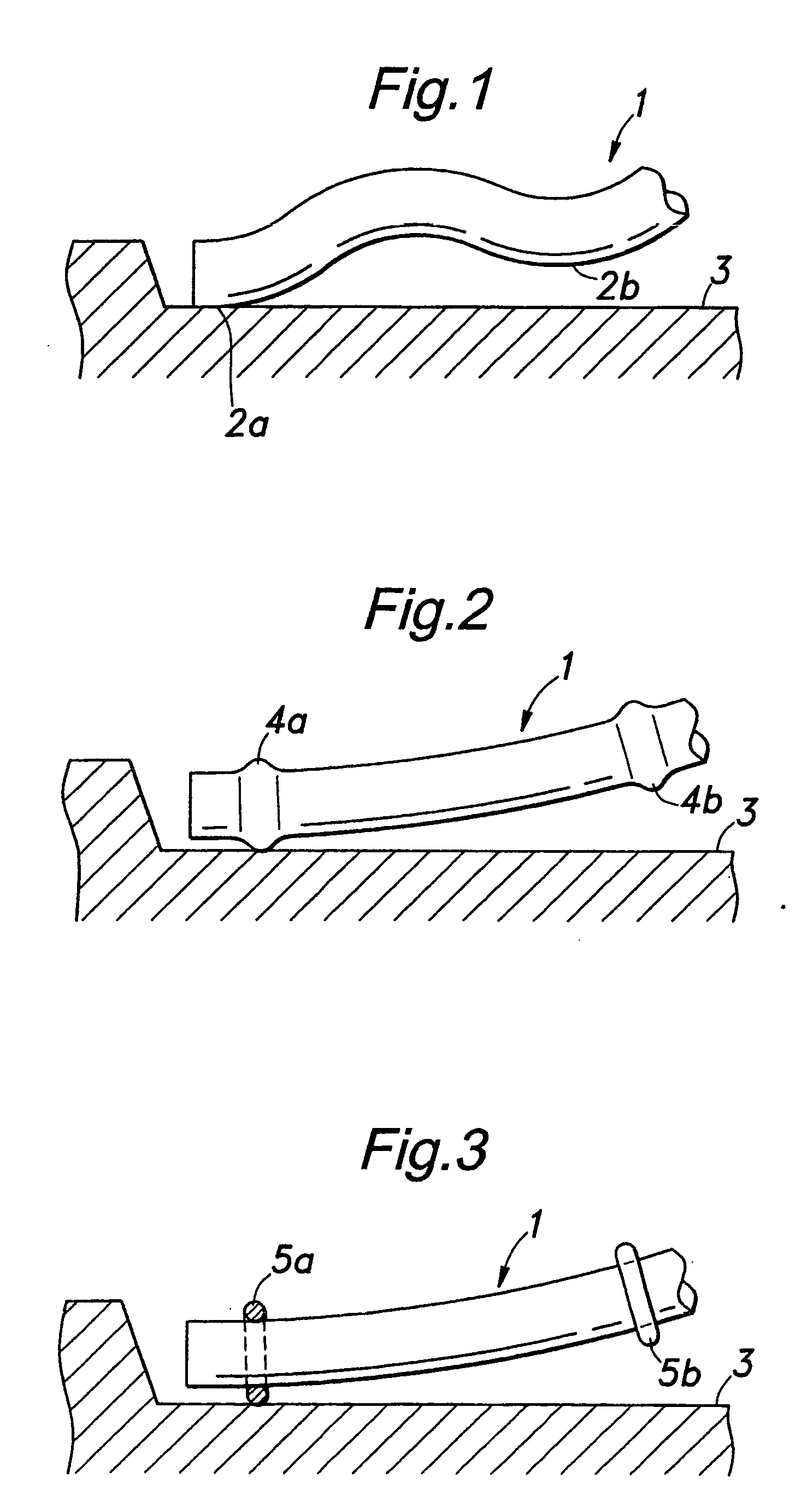
[0034]FIG. 1 shows an exemplary end turn of a coil spring embodying the present invention. The end turn 1 of this coil spring consists of an open end coil turn, and is provided with a wavy shape as represented by a plurality of bends 2a and 2b. As a result, the contact between the end turn 1 and a spring seat 3 is effected substantially as a point contact, instead of a line contact. According to the prior art, the length of contact between the end turn and the spring seat increased with the increase in the load.

[0035] However, according to the illustrated embodiment, the part of the coil wire located between the two bends 2a and 2b is spaced from the spring seat 3, and thereby remains to be effective as a part of effective turns during the time the load is increased from a value by which only one of the bends 2a is in contact with the spring seat 3 to a value by which the next bend 2b is also brought into contact with the spring seat 3. In other words, because the contact position ...


PUM


Abstract

In a compression coil spring device, suitable for use in a strut wheel suspension system, including a coil wire wound into a coil having an end turn, the end turn is adapted to be supported by a spring seat at one or a plurality of discrete points. This can be accomplished either by providing a plurality of projections on the coil wire along the length of the coil wire of the end turn, with the remainder of the coil wire being substantially free of projections, or by providing a plurality of projections for supporting the end turn at one or a plurality of discrete points of the spring seat. Thus, the spring demonstrates the same property with regard to the centroid of contact pressure or line of action of the spring force, and the spring constant, without regard to the spring load as long as the spring end is supported by the same discrete contact point or points. In other words, the changes in the number of effective turns depending on the magnitude of the load can be minimized so that the relationship between the load and compression stroke can be made substantially linear, and the change in the angle of the axis of the spring force can be minimized. Also, in the above structure, the end turn contacts the spring seat only at the predetermined projections, and this minimizes the variation in the spring property, frictional resistance between the contacting members and bending moment relating to individual coil springs.

Description

RELATED APPLICATION [0001] The present application is a continuation-in-part of application Ser. No. 10 / 496,393, filed Nov. 8, 2004, for Compression Coil Spring Device Having A Discrete Support, which is the National Phase entry into the United States of Patent Cooperation Treaty Application Serial No. PCT / JP02 / 12267, filed Nov. 25, 2002. application Ser. No. 10 / 496,393 is pending as of the filing date of the present application. U.S. patent application Ser. No. 10 / 496,393 is hereby incorporated by reference as if set forth in its' entirety herein.TECHNICAL FIELD [0002] The present invention relates to a compression coil spring device. More particularly, the present invention relates to a compression coil spring device having an open-coil configuration. Most particularly, the present invention to a compression coil spring device having an open-coil configuration which is open at one or both ends and not ground at the open end(s) and which is suitable for use in a strut wheel suspens...

Claims


Application Information

Patent Timeline
Patent Type & Authority Applications(United States)
IPC IPC(8): F16F1/12
CPCF16F1/126F16F1/12
Inventor UMEZAWA, MASAHIROKATO, TOMOTAKEHAMANO, TOSHIOUEDA, MASANAO
Owner NHK SPRING CO LTD
Why Eureka
Try Eureka