
Ethernet connection-based forwarding process

Inactive Publication Date: 2007-08-02
JU YU
View PDF23 Cites 121 Cited by
  • Summary
  • Abstract
  • Description
  • Claims
  • Application Information

AI Technical Summary

Benefits of technology

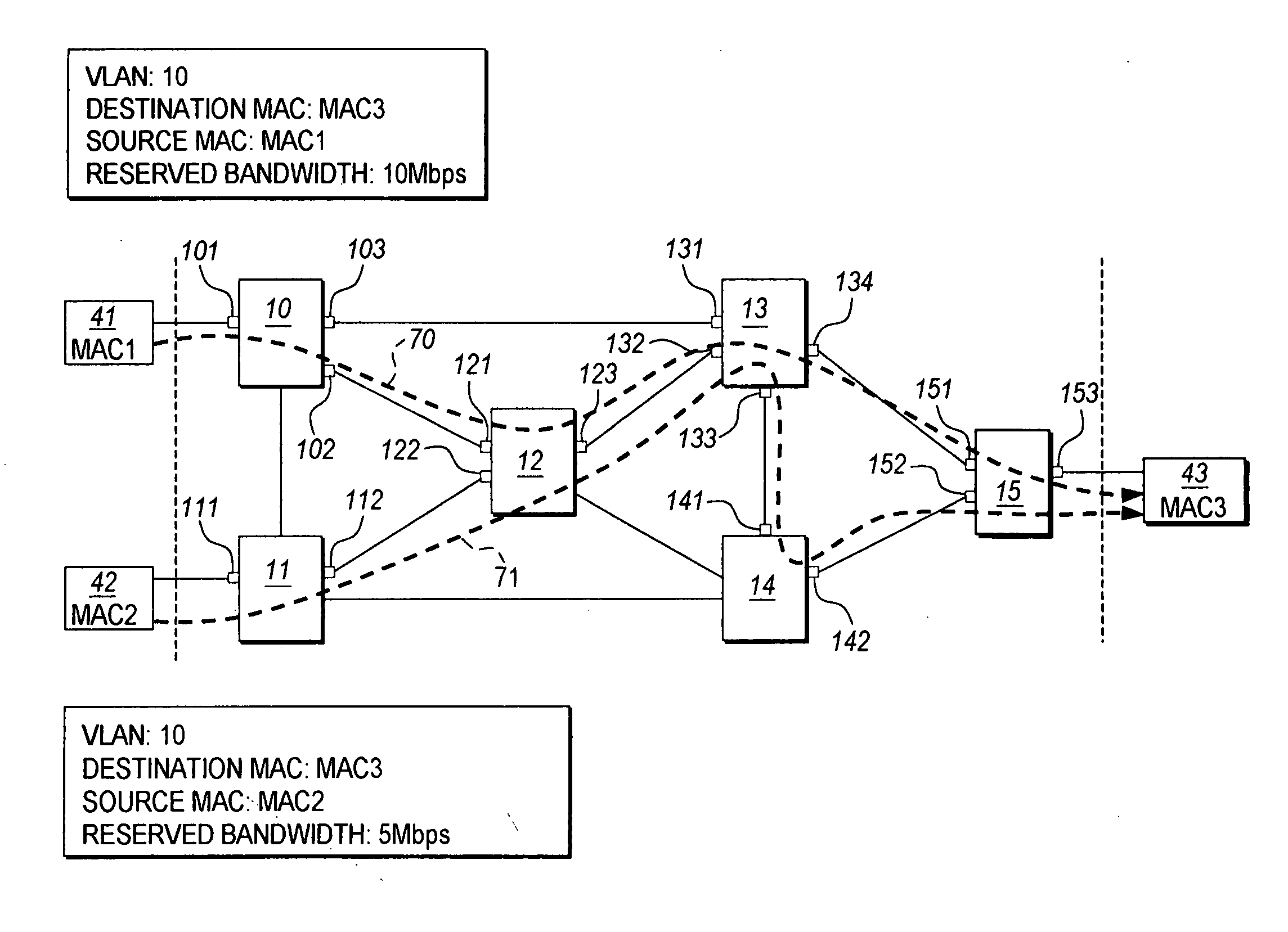
[0019] The present invention allows for provisioning connections across the Ethernet network, thus enabling streams of frame data having a same destination MAC address to be merged and separated en-route to the destination, so that an Ethernet carrier may satisfy a customer's QoS requirements. According to the connection based forwarding process of the present invention, an Ethernet carrier can put all bridge ports into a connection-based forwarding state, thus fully utilizing all of the network's physically available bridge ports.
[0020] A provisioned connection also eliminates the requirement of a loop free active topology. The present invention also eliminates the requirement of spanning tree protocols, thus allowing for all bridge ports to be accessed for forwarding of Ethernet frame data.

Problems solved by technology

The result is that under conventional Ethernet network topology, network resources (i.e. bridge ports) are not used efficiently.
The aforementioned look up process makes network resource allocation along the forwarding path to guarantee the QoS requirements demanded by traffic flow infeasible because knowledge of a destination MAC address alone does not provide sufficient information to uniquely identify a traffic flow within the Ethernet network.
Moreover, lookup results usually change when active topology changes, thus making the forwarding path for Ethernet frames unpredictable.
Therefore, conventional Ethernet networks do not provide end-to-end QoS.
However, in the event that a destination address corresponding to a destination node of the connection and an identifier, such as a VLAN tag to establish a connection are used, there still exists the problem that these aforementioned methods, even with increased addressing power of the 60 bit label, cannot differentiate data frames with the same destination MAC address and VLAN tag, but having a different source MAC address.
It should be noted that QoS cannot be guaranteed for two such connections, since two merged connections starting from a common switch cannot be differentiated.

Method used


Image

  • Ethernet connection-based forwarding process
  • Ethernet connection-based forwarding process
  • Ethernet connection-based forwarding process

Examples


Embodiment Construction

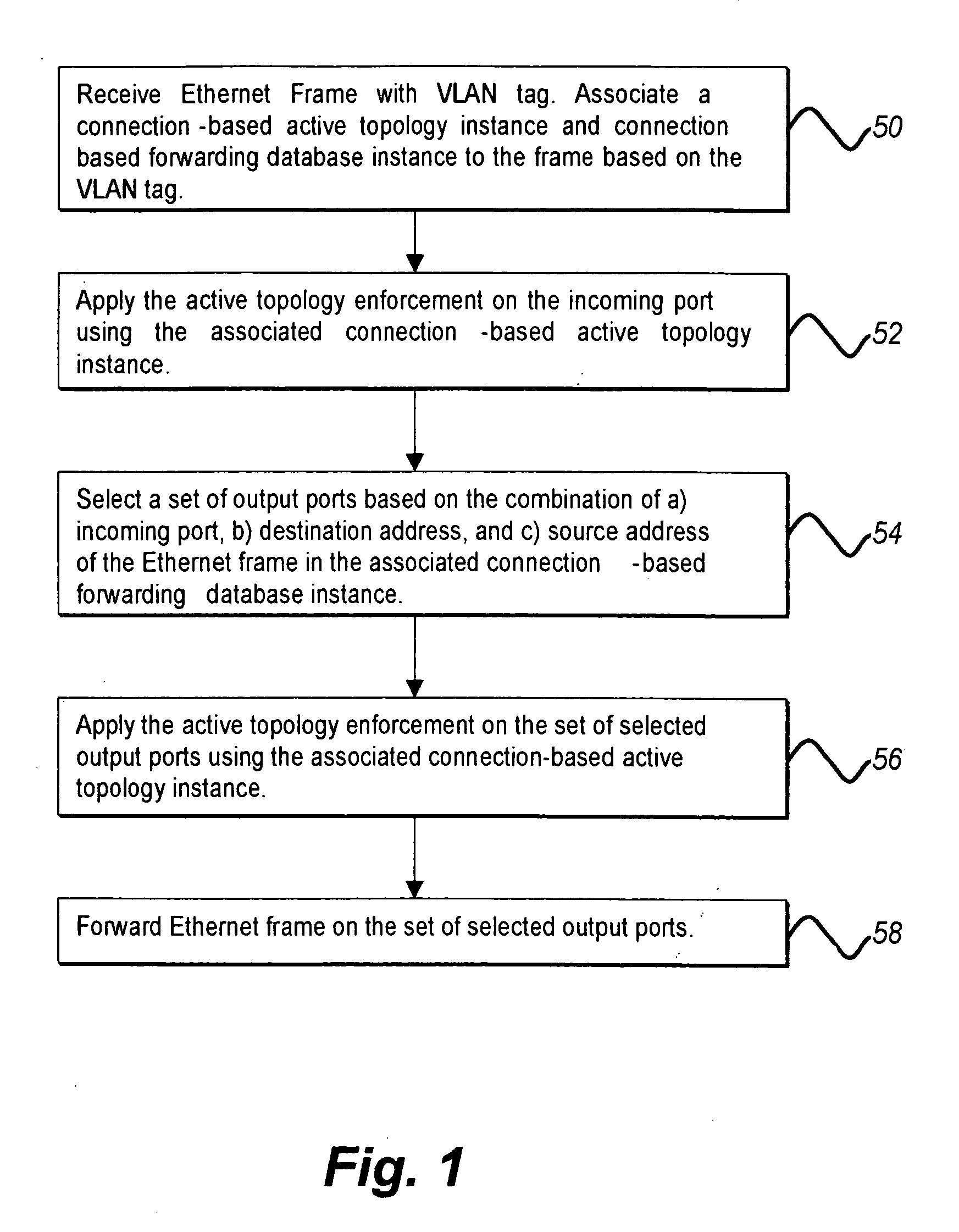
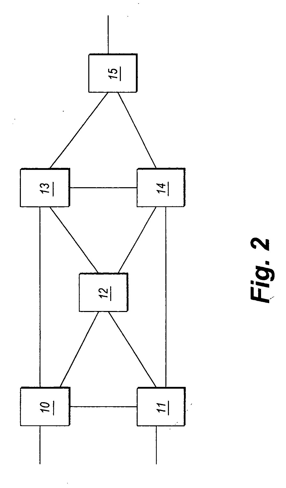
[0030] The present invention is a system and method of establishing a pre-determined transmission path by utilizing frame transmission filters based on an incoming port, a source MAC address, and a destination MAC address, before communicating frames of data over an Ethernet connection. FIG. 2 depicts a typical hardware mesh of switches, such as switches 10 through 15. The present invention has the capability to reserve resources on each of the Ethernet switches 10 through 15 which may be on a desired communications path, through setting up connection based forwarding tables functioning as filters in a database instance having mapping information related to an incoming port, a source MAC address, and a destination MAC address.

[0031] The Ethernet connection-based forwarding process of the present invention allows for provisioning connections across the Ethernet network so that an Ethernet carrier, i.e., service provider, may satisfy a customer's QoS requirements. A provisioned conne...


PUM


Abstract

The Ethernet connection-based forwarding process is a system and method of establishing a pre-determined transmission path before communicating frames of data over an Ethernet connection. The present invention supports reserving resources on each of the Ethernet switches which may be on a desired communications path while setting up the connection based forwarding tables. The present invention can differentiate two connections having the same destination MAC address but different source MAC addresses so that streams of frame data from the different sources can be merged and separated en-route to the destination, thus making it possible to reserve proper resources on the switches for a connection thereby satisfying QoS requirements for the connection. A provisioned connection also eliminates the requirement of a loop free active topology. The present invention also eliminates the requirement of spanning tree protocols so that all bridge ports may be accessed for forwarding of Ethernet frame data.

Description

BACKGROUND OF THE INVENTION [0001] 1. Field of the Invention [0002] The present invention relates to connection based forwarding of Ethernet data frames. [0003] 2. Description of the Related Art [0004] Ethernet is a network technology defined by the LAN / MAN Standards Committee of the IEEE Computer Society. It is specified in a family of IEEE 802 Standards. “IEEE Std 802—Overview and Architecture” provides an overview to the family of IEEE 802 Standards. An Ethernet network comprises Ethernet switches interconnected by links. Conventional Ethernet provides a connectionless technology. From the perspective of the Open Standards Interconnect (OSI) hierarchy of data communications, the Ethernet switches, bridges, and the like, operate in the domain of OSI layer 2. [0005] As is well known in the art, conventional Ethernet networks use spanning tree protocols to increase network traffic efficiencies by detecting physical loops and logically disabling connections, i.e., blocking some of th...

Claims


Application Information

Patent Timeline
IPC IPC(8): H04L12/56
CPCH04L12/4641H04L12/5695H04L41/0806H04L41/12H04L47/806H04L45/04H04L45/16H04L47/724H04L45/00H04L47/70
Inventor JU, YU
Owner JU YU
Learn More