
Posterior joint replacement device

a joint replacement and anterior joint technology, applied in the direction of prosthesis, spinal implants, coatings, etc., can solve the problems of increasing the difficulty of second treatment, introducing additional distress to the patient, and invasive and intensive spinal disc inserting procedures

Active Publication Date: 2007-08-02
3SPINE INC
View PDF99 Cites 130 Cited by
  • Summary
  • Abstract
  • Description
  • Claims
  • Application Information

AI Technical Summary

Benefits of technology

"The patent text describes a prosthetic device for replacing a damaged spinal disc to provide articulating motion to the upper and lower vertebrae. The device includes an upper and lower articular portion that can be placed in the intervertebral space. The device can be used as a joint replacement or to treat degenerative disc disease. The device has a posterior section that interacts with another device during articulation. The device can be implanted on either the right or left side of the intervertebral space. The patent text also describes several variations of the device, including different methods for placement and interaction between the upper and lower articular portions. The technical effects of the patent text include improved spinal motion and reduced pain and discomfort for patients with degenerative disc disease."

Problems solved by technology

While the inserted disc may provide joint articulation to a patient, inserting the spinal disc can be an invasive and intensive procedure.
Further, because scar tissue may grow about the surgical site, any required second treatment can be more difficult, and may introduce additional distress to the patient.

Method used


Image

  • Posterior joint replacement device
  • Posterior joint replacement device
  • Posterior joint replacement device

Examples


Embodiment Construction

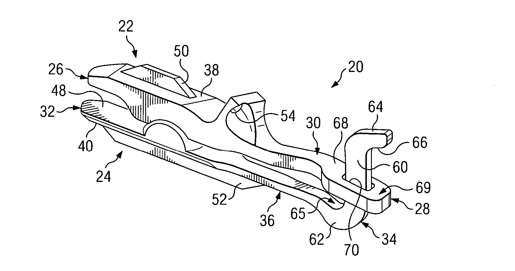
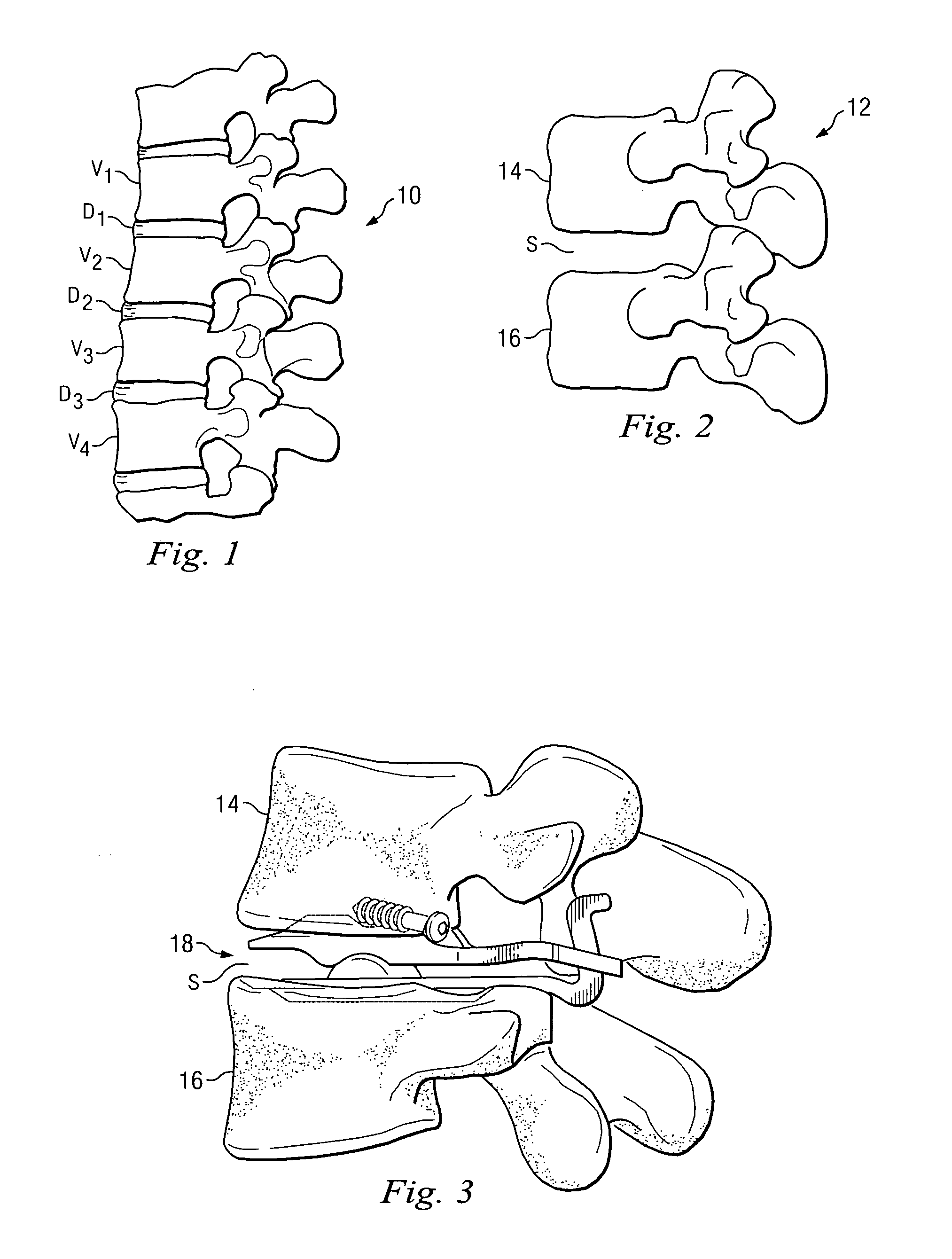
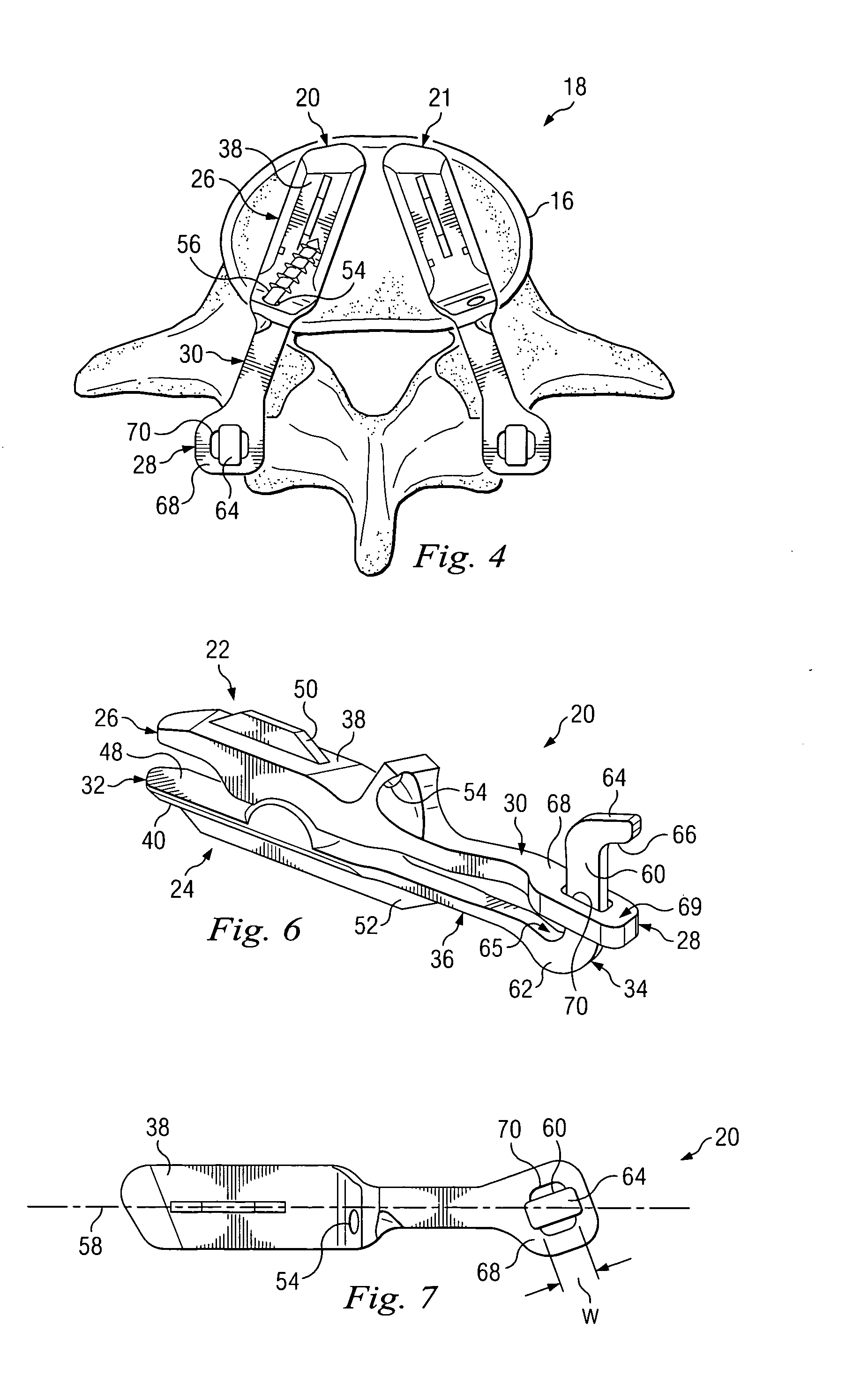
[0027] The present invention relates generally to vertebral reconstructive devices and, more particularly, to an intervertebral prosthetic device for implantation. For the purposes of promoting an understanding of the principles of the invention, reference will now be made to embodiments or examples illustrated in the drawings and specific language will be used to describe the same. It will nevertheless be understood that no limitation of the scope of the invention is thereby intended. Any alterations and further modifications in the described embodiments, and any further applications of the principles of the invention as described herein are contemplated as would normally occur to one skilled in the art to which the invention relates.

[0028]FIG. 1 shows a lateral view of a portion of a spinal column 10, illustrating a group of adjacent upper and lower vertebrae V1, V2, V3, V4 separated by natural intervertebral discs D1, D2, D3. The illustration of four vertebrae is only intended a...


PUM

PropertyMeasurementUnit
angleaaaaaaaaaa
frictionaaaaaaaaaa
resistanceaaaaaaaaaa

Abstract

A prosthetic device for posterior placement in an intervertebral space defined between an upper vertebrae and a lower vertebrae may include an upper articular portion configured to be at least partially disposed in the intervertebral space and a lower articular portion configured to be at least partially disposed in the intervertebral space below the upper articular portion, the upper and lower articular portions being configured to provide articulating motion to the upper and lower vertebrae. The upper and lower articular portions each may include a posterior section configured to be disposed in a location posterior of the intervertebral space. The posterior section of one of the upper and lower articular portions may include a post, and the posterior section of the other of the upper and lower articular portions may include a receiving portion configured to interact with the post during articulation.

Description

BACKGROUND [0001] Disc arthroplasty is one way of treating injured, degraded, or diseased spinal discs. Some disc arthroplasty treatments include replacing injured discs of the joint with a motion-preserving spinal disc that allows some articulation or movement of the spinal joint. While the inserted disc may provide joint articulation to a patient, inserting the spinal disc can be an invasive and intensive procedure. For example, anterior procedures often require displacement of organs, such as the aorta and vena cava, and must be performed with great care. Further, because scar tissue may grow about the surgical site, any required second treatment can be more difficult, and may introduce additional distress to the patient. [0002] What is needed is a prosthetic device for insertion into an intervertebral space that may be installed from a posterior position. The posterior joint replacement device disclosed herein overcomes one or more problems in the prior art. SUMMARY OF THE INVEN...

Claims


Application Information

Patent Timeline
Patent Type & Authority Applications(United States)
IPC IPC(8): A61F2/44
CPCA61F2/4405A61F2310/00976A61F2002/2817A61F2002/30369A61F2002/3037A61F2002/30405A61F2002/30563A61F2002/30565A61F2002/30578A61F2002/30662A61F2002/30841A61F2002/30884A61F2002/30924A61F2002/30925A61F2002/443A61F2002/448A61F2220/0025A61F2220/0033A61F2310/00017A61F2310/00023A61F2310/00029A61F2310/00161A61F2310/00167A61F2310/00203A61F2310/00239A61F2310/00796A61F2/4425A61F2002/30922A61F2/44
Inventor BRADDOCK, DANNY H. JR.PETERMAN, MARC M.HODGES, SCOTT D.YU, KIDONGHUMPHREYS, STEVEN C.
Owner 3SPINE INC
Learn More