
Shoulder prosthesis and a system for implanting a shoulder prosthesis

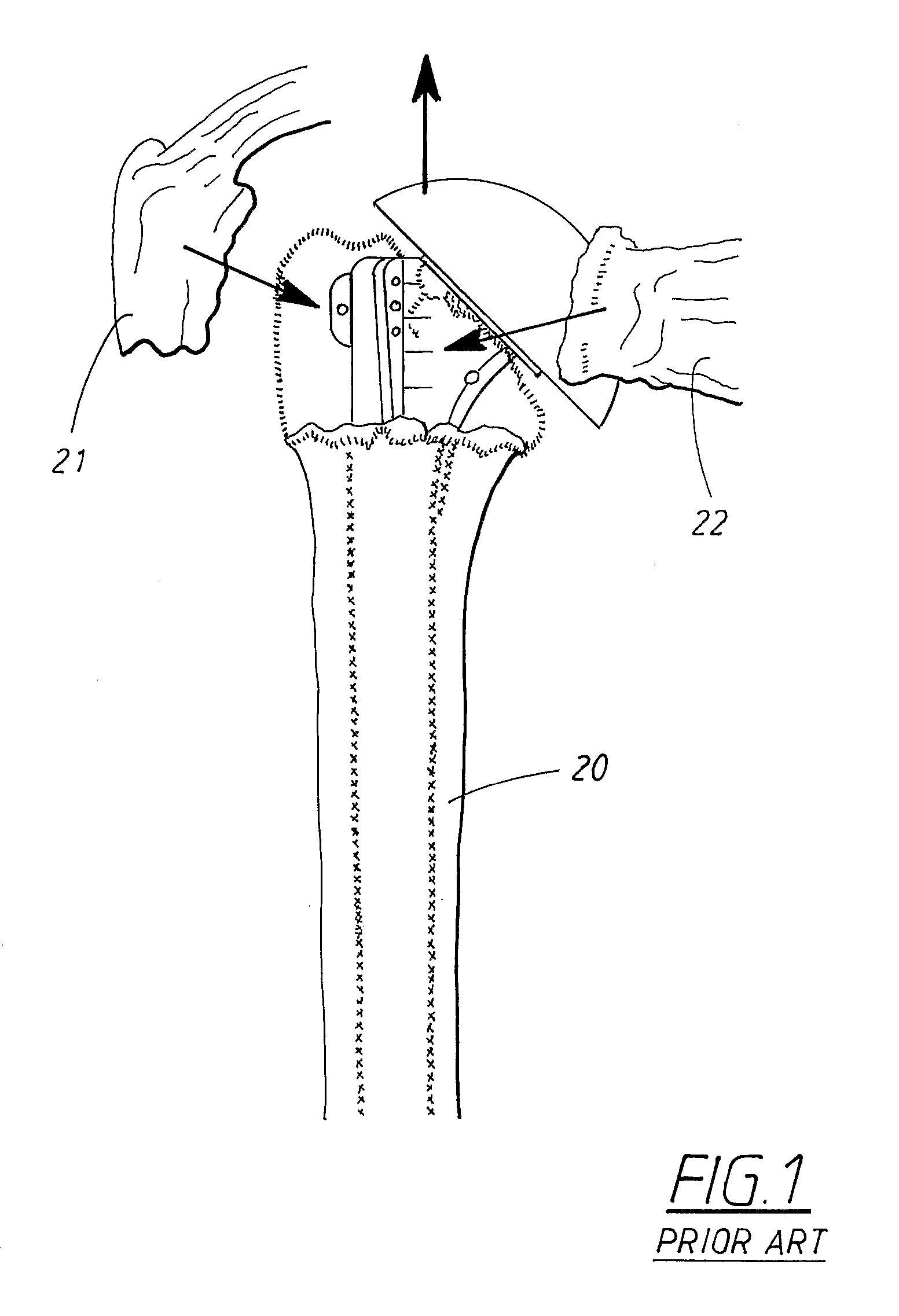
a shoulder and prosthesis technology, applied in the field of shoulder prosthesis and system for implanting shoulder prosthesis, can solve the problems of tubercles not being fully stabilized, tubercles not being inserted,

Inactive Publication Date: 2007-08-02
EKHOLM CARL +1
View PDF4 Cites 12 Cited by
  • Summary
  • Abstract
  • Description
  • Claims
  • Application Information

AI Technical Summary

Problems solved by technology

With existing designs problems still exist re the insertion of the tubercles.
None of these sutures attach the tubercle at their normal centre of pull—hence the tubercles will not become fully stabilized.

Method used


Image

  • Shoulder prosthesis and a system for implanting a shoulder prosthesis
  • Shoulder prosthesis and a system for implanting a shoulder prosthesis
  • Shoulder prosthesis and a system for implanting a shoulder prosthesis

Examples


Embodiment Construction

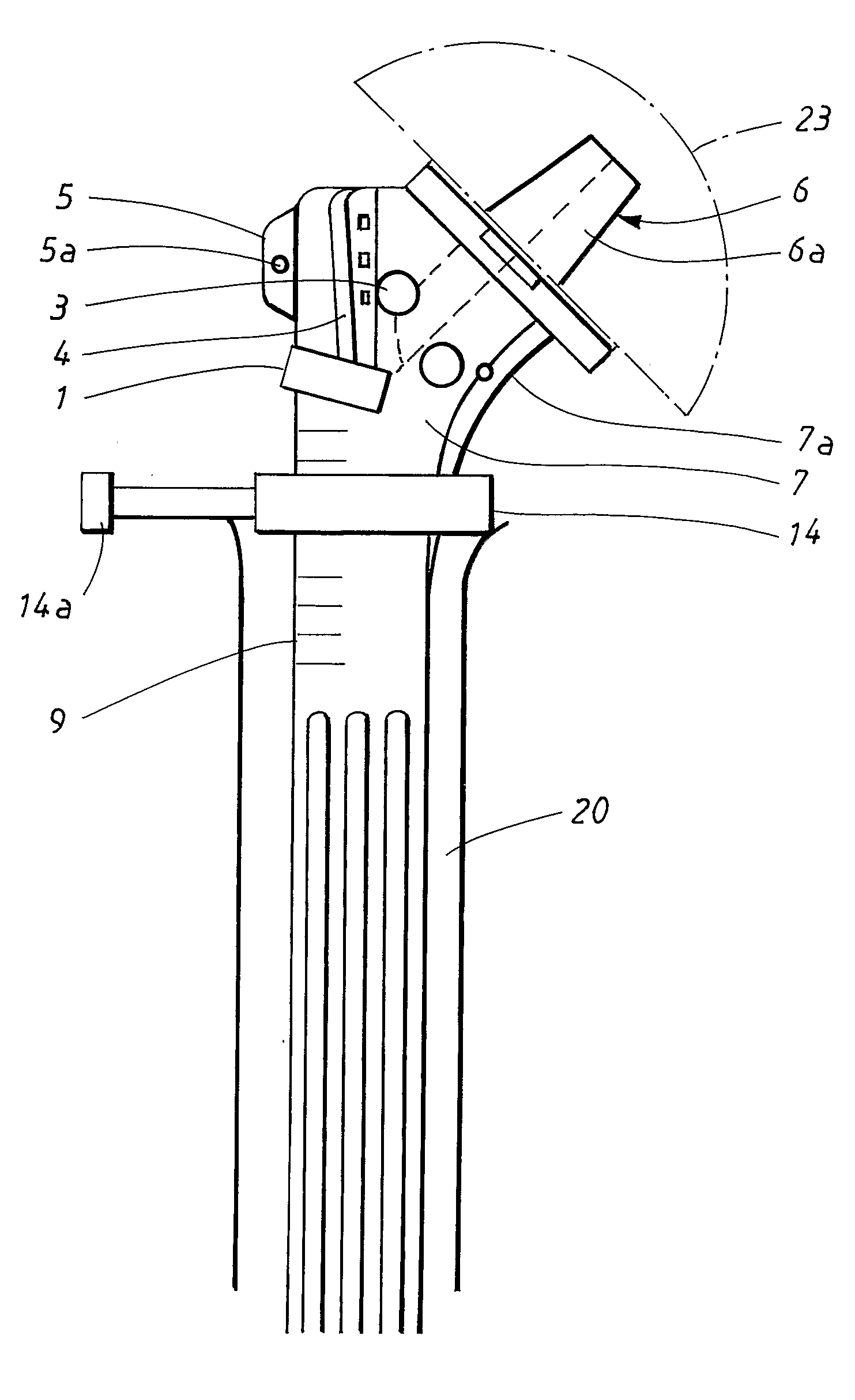
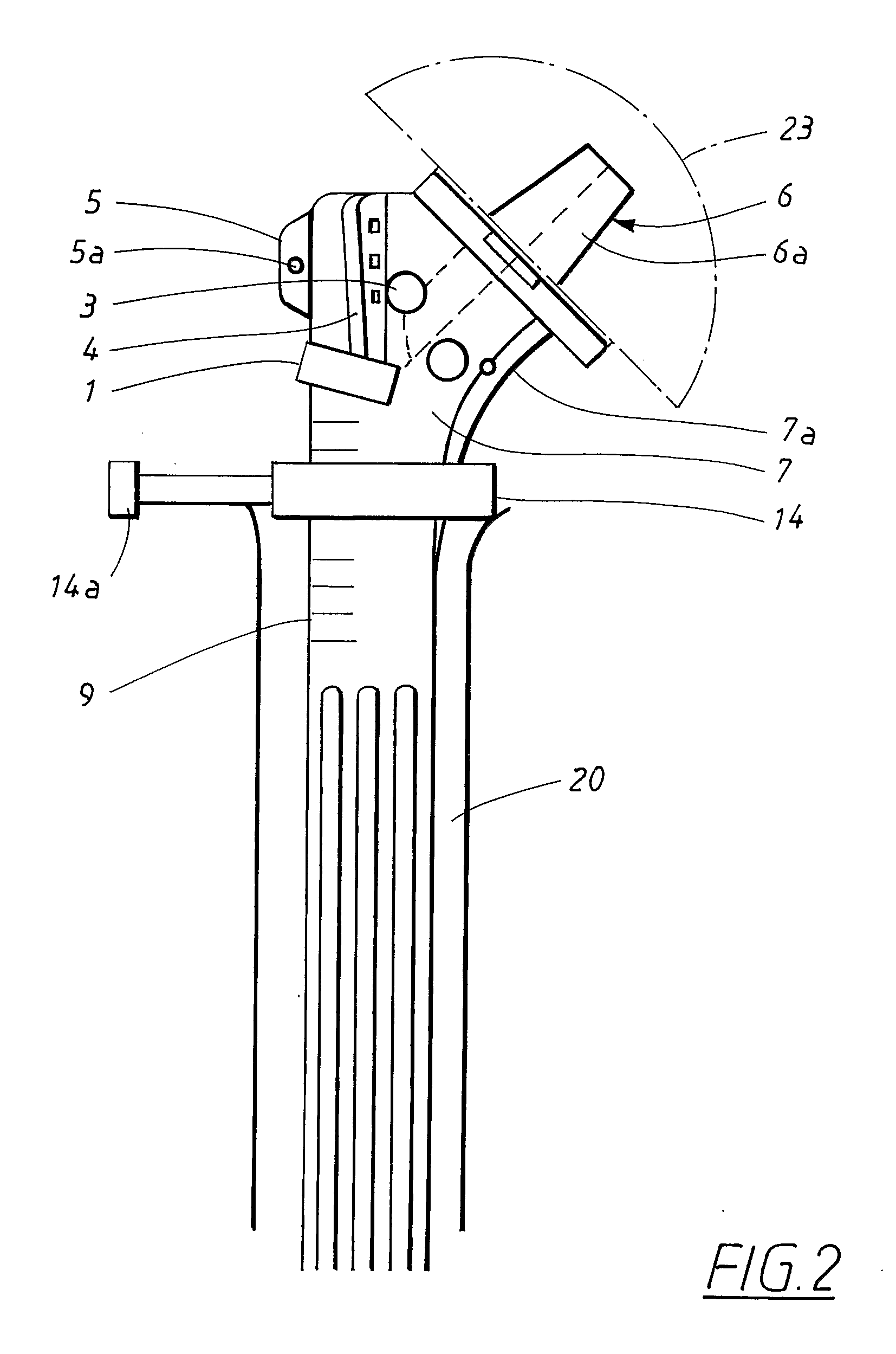
[0017] The main parts of the shoulder prosthesis and the system for implanting a shoulder prosthesis into a human being according to the present invention are as follows: [0018] hole 1 for lateral anchoring screw 1a (directed slightly distally to leave room for anterior hole) [0019] hole 2 for anterior anchoring screw 2a [0020] hole 3 for targeting arm 10 attachment [0021] hole 4 in anterior fin, also accepting targeting arm stabilizing peg [0022] lateral fin 5[0023] male part 6a of Morse taper 6[0024] suture hole 7a at medial neck 7[0025] prosthesis top end 8 (lateral view) being tapered [0026] etch marks 9[0027] targeting arm 10[0028] peg 11 of targeting arm [0029] sleeve 12 for guiding lateral screw [0030] sleeve 13 for guiding anterior screw [0031] adjustable ring 14 supported by the locking screw against the fracture [0032] guide wire 15 for posterior cannulated screw 16a [0033] hole 16 for posterior screw 16a

[0034] The principal aspects of the system according to the present ...


PUM


Abstract

Shoulder prosthesis, including a stem provided to be inserted into a canal of the humerus shaft, a neck and a head supported by the neck. The neck is provided with two holes (1, 2) for anchoring screws (1a, 2a), namely a first hole (1) for a lateral anchoring screw (1a) and a second hole (2) for an anterior anchoring screw (2a). The lateral anchoring screw is provided to attach a first tubercle laterally to the neck and the anterior anchoring screw is provided to attach a second tubercle anterior to the neck. A system for implanting a shoulder prosthesis, comprises a targeting arm attachable to the neck of the prosthesis and is provided with guide means for guiding anchoring screws (1a, 2a) to be screwed into at least a lateral hole (1) and an anterior hole (2) in the neck. The targeting arm is also provided for holding a trial prosthesis.

Description

TECHNICAL FIELD [0001] The present invention relates to a shoulder prosthesis and a system for implanting a shoulder prosthesis according to the preamble of claims 1 and 5 respectively. [0002] 1. Background Art [0003] Replacement is undertaken in fresh fractures when functional repair of the humeral head is deemed impossible. The goal is of course to make the shoulder pain free and to reconstruct the joint for restored range of motion. The similar approach is standard procedure for femoral neck fractures and produces excellent results. Although shoulder hemi replacement arthroplasty works well with the rheumatoid and arthritic shoulder, humeral head replacement in the fracture situation has been less successful particularly regarding the range of motion obtained. The reason for this may not be perfectly clear but several explanations can be put forward. [0004] In the fractured shoulder anatomy is distorted and landmarks may be lost. It may therefore be difficult to judge exactly how...

Claims


Application Information

Patent Timeline
Patent Type & Authority Applications(United States)
IPC IPC(8): A61F2/40A61F2/46A61FA61F2/00A61F2/30
CPCA61B17/842A61F2/4059A61F2/4612A61F2/4684A61F2250/0097A61F2002/30729A61F2002/30772A61F2002/30884A61F2002/30899A61F2002/30617
Inventor EKHOLM, CARLJONSSON, ANDERS
Owner EKHOLM CARL
Learn More